H36.1 General.
H36.3 Reference Test Conditions.
H36.5 Symbols and Units.
PART B -- NOISE MEASUREMENT UNDER §36.801
H36.101 Noise certification test and measurement conditions.
H36.103 Takeoff test conditions.
H36.105 Flyover test conditions.
H36.107 Approach test conditions.
H36.109 Measurement of helicopter noise received on the ground.
H36.111 Reporting and correcting measured data.
H36.113 Atmospheric attenuation of sound.
PART C -- NOISE EVALUATION AND CALCULATION UNDER §36.803
H36.201 Noise evaluation in EPNdB.
H36.203 Calculation of noise levels.
H36.205 Detailed data correction procedures.
PART D -- NOISE LIMITS UNDER §36.805
H36.301 Noise measurement, evaluation, and calculation.
H36.303 [Reserved]
H36.305 Noise levels.
PART A -- REFERENCE CONDITIONS
Section H36.1 General. This appendix prescribes noise
requirements for helicopters specified under §36.1, including:
(a) The conditions under which helicopter noise certification tests
under Part H must be conducted and the measurement procedures that must be
used under §36.801 to measure helicopter noise during each test;
(b) The procedures which must be used under §36.803 to correct the
measured data to the reference conditions and to calculate the noise
evaluation quantity designated as Effective Perceived Noise Level (EPNL);
and
(c) The noise limits for which compliance must be shown under §36.805.
Section H36.3 Reference Test Conditions.
(a) Meteorological conditions. Aircraft position, performance
data and noise measurements must be corrected to the following noise
certification reference atmospheric conditions which shall be assumed to
exist from the surface to the aircraft altitude:
(1) Sea level pressure of 2116 psf (76 cm mercury).
(2) Ambient temperature of 77 degrees F (25 degrees C).
(3) Relative humidity of 70 percent.
(4) Zero wind.
(b) Reference test site. The reference test site is flat and
without line-of-sight obstructions across the flight path that encompasses
the 10 dB down points.
(c) Takeoff reference profile. (1) Figure H1 illustrates a
typical takeoff profile, including reference conditions.
(2) The reference flight path is defined as a straight line segment
inclined from the starting point (1640 feet prior to the center microphone
location at 65 feet above ground level) at an angleβ defined by the
certificated best rate of climb and Vy for minimum engine
performance. The constant climb angleβ is derived from the manufacturer's
data (FAA-approved by the FAA) to define the flight profile for the
reference conditions. The constant climb angleβ is drawn through Cr
and continues, crossing over station A, to the position corresponding to
the end of the type certification takeoff path represented by position Ir.
(d) Level flyover reference profile. The beginning of the level
flyover reference profile is represented by helicopter position D (Figure
H2). The helicopter approaches position D in level flight 492 feet above
ground level as measured at station A. Airspeed is stabilized at either
0.9 VH or 0.45 VH + 65 knots (0.45 VH
+ 120 km/hr), whichever speed is less. Rotor speed is stabilized at the
maximum continuous RPM throughout the 10 dB down time period. The
helicopter crosses station A in level flight and proceeds to position J.
(e) For noise certification purposes, VH is defined as the
airspeed in level flight obtained using the minimum specification engine
torque corresponding to maximum continuous power available for sea level,
25 °C ambient conditions at the relevant maximum certificated weight. The
value of VH thus defined must be listed in the Rotorcraft
Flight Manual.
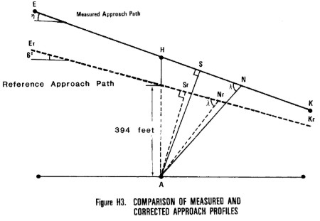
(f) Approach reference profile. (1) Figure H3 illustrates
approach profile, including reference conditions.
(i) The beginning of the approach profile is represented by helicopter
position E. The position of the helicopter is recorded for a sufficient
distance (EK) to ensure recording of the entire interval during which the
measured helicopter noise level is within 10 dB of Maximum Tone Corrected
Perceived Noise Level (PNLTM), as required. EK represents a stable flight
condition in terms of torque, rpm, indicated airspeed, and rate of descent
resulting in a 6° ±0.5° approach angle.
(ii) The approach profile is defined by the approach angle β passing
directly over the station A at a height of AH, to position K, which
terminates the approach noise certification profile.
(2) The helicopter approaches position H along a constant 6° approach
slope throughout the 10 dB down time period. The helicopter crosses
position E and proceeds along the approach slope crossing over station A
until it reaches position K.
Section H36.5 Symbols and units. The following symbols and units
as used in this appendix for helicopter noise certification have the
following meanings.
                 Flight Profile Identification_Positions
------------------------------------------------------------------------
             Position                           Description
------------------------------------------------------------------------
A................................  Location of the noise measuring point
                                    at the flight-track noise measuring
                                    station vertically below the
                                    reference (takeoff, flyover, or
                                    approach) flight path.
C................................  Start of noise certification takeoff
                                    flight path.
C[INF]r[/INF]....................  Start of noise certification
                                    reference takeoff flight path.
D................................  Start of noise certification flyover
                                    flight path.
D[INF]r[/INF]....................  Start of noise certification
                                    reference flyover path.
E................................  Start of noise certification approach
                                    flight path.
E[INF]r[/INF]....................  Start of noise certification
                                    reference approach flight path.
F................................  Position on takeoff flight path
                                    directly above noise measuring
                                    station A.
G................................  Position on flyover flight path
                                    directly above noise measuring
                                    station A.
H................................  Position on approach flight path
                                    directly above noise measuring
                                    station A.
I................................  End of noise type certification
                                    takeoff flight path.
I[INF]r[/INF]....................  End of noise type certification
                                    reference takeoff flight path.
J................................  End of noise type certification
                                    flyover flight path.
J[INF]r[/INF]....................  End of noise type certification
                                    reference flyover flight path.
K................................  End of noise certification approach
                                    type flight path.
K[INF]r[/INF]....................  End of noise type certification
                                    reference approach flight path.
L................................  Position on measured takeoff flight
                                    path corresponding to PNLTM at
                                    station A.
L[INF]r[/INF]....................  Position on reference takeoff flight
                                    path corresponding to PNLTM of
                                    station A.
M................................  Position on measured flyover flight
                                    path corresponding to PNLTM of
                                    station A.
M[INF]r[/INF]....................  Position on reference flyover flight
                                    path corresponding to PNLTM of
                                    station A.
N................................  Position on measured approach flight
                                    path corresponding to PNLTM at
                                    station A.
N[INF]r[/INF]....................  Position on reference approach flight
                                    path corresponding to PNLTM at
                                    station A.
S................................  Position on measured approach path
                                    nearest to station A.
S[INF]r[/INF]....................  Position on reference approach path
                                    nearest to station A.
T................................  Position on measured takeoff path
                                    nearest to station A.
T[INF]r[/INF]....................  Position on reference takeoff path
                                    nearest to station A.
------------------------------------------------------------------------
                        Flight Profile Distances
------------------------------------------------------------------------
        Distance                Unit                   Meaning
------------------------------------------------------------------------
AF.....................  Feet..............  Takeoff Height. The
                                              vertical distance between
                                              helicopter and station A.
AG.....................  Feet..............  Flyover Height. The
                                              vertical distance between
                                              the helicopter and station
                                              A.
AH.....................  Feet..............  Approach Height. The
                                              vertical distance between
                                              the helicopter and station
                                              A.
AL.....................  Feet..............  Measured Takeoff Noise
                                              Path. The distance from
                                              station A to the measured
                                              helicopter position L.
AL[INF]r[/INF].........  Feet..............  Reference Takeoff Noise
                                              Path. The distance from
                                              station A to the reference
                                              helicopter position
                                              L[INF]r[/INF].
AM.....................  Feet..............  Measured Flyover Noise
                                              Path. The distance from
                                              station A to the measured
                                              helicopter position M.
AM[INF]r[/INF].........  Feet..............  Reference Flyover Noise
                                              Path. The distance from
                                              station A to helicopter
                                              position M[INF]r[/INF] on
                                              the reference flyover
                                              flight path.
AN.....................  Feet..............  Measured Approach Noise
                                              Path. The distance from
                                              station A to the measured
                                              helicopter noise position
                                              N.
AN[INF]r[/INF].........  Feet..............  Reference Approach Noise
                                              Path. The distance from
                                              station A to the reference
                                              helicopter position
                                              N[INF]r[/INF].
AS.....................  Feet..............  Measured Approach Minimum
                                              Distance. The distance
                                              from station A to the
                                              position S on the measured
                                              approach flight path.
AS[INF]r[/INF].........  Feet..............  Reference Approach Minimum
                                              Distance. The distance
                                              from station A to the
                                              position S[INF]r[/INF] on
                                              the reference approach
                                              flight path.
AT.....................  Feet..............  Measured Takeoff Minimum
                                              Distance. The distance
                                              from station A to the
                                              position T on the measured
                                              takeoff flight path.
AT[INF]r[/INF].........  Feet..............  Reference Takeoff Minimum
                                              Distance. The distance
                                              from station A to the
                                              position T[INF]r[/INF] on
                                              the reference takeoff
                                              flight path.
CI.....................  Feet..............  Takeoff Flight Path
                                              Distance. The distance
                                              from position C at which
                                              the helicopter establishes
                                              a constant climb angle on
                                              the takeoff flight path
                                              passing over station A and
                                              continuing to position I
                                              at which the position of
                                              the helicopter need no
                                              longer be recorded.
DJ.....................  Feet..............  Flyover Flight Path
                                              Distance. The distance
                                              from position D at which
                                              the helicopter is
                                              established on the flyover
                                              flight path passing over
                                              station A and continuing
                                              to position J at which the
                                              position of the helicopter
                                              need no longer be
                                              recorded.
EK.....................  Feet..............  Approach Flight Path
                                              Distance. The distance
                                              from position E at which
                                              the helicopter establishes
                                              a constant angle on the
                                              approach flight path
                                              passing over station A and
                                              continuing to position K
                                              at which the position of
                                              the helicopter need no
                                              longer be recorded.
------------------------------------------------------------------------
PART B -- NOISE MEASUREMENT UNDER §36.801
Section H36.101 Noise certification test and measurement conditions.
(a) General. This section prescribes the conditions under which
aircraft noise certification tests must be conducted and the measurement
procedures that must be used to measure helicopter noise during each test.
(b) Test site requirements. (1) Tests to show compliance with
established helicopter noise certification levels must consist of a series
of takeoffs, level flyovers, and approaches during which measurement must
be taken at noise measuring stations located at the measuring points
prescribed in this section.
(2) Each takeoff test, flyover test, and approach test includes
simultaneous measurements at the flight-track noise measuring station
vertically below the reference flight path and at two sideline noise
measuring stations, one on each side of the reference flight track 492
feet (150m) from, and on a line perpendicular to, the flight track of the
noise measuring station.
(3) The difference between the elevation of either sideline noise
measuring station may not differ from the flight-track noise measuring
station by more than 20 feet.
(4) Each noise measuring station must be surrounded by terrain having
no excessive sound absorption characteristics, such as might be caused by
thick, matted, or tall grass, shrubs, or wooded areas.
(5) During the period when the takeoff, flyover, or approach noise/time
record indicates the noise measurement is within 10 dB of PNLTM, no
obstruction that significantly influences the sound field from the
aircraft may exist --
(i) For any flight-track or sideline noise measuring station, within a
conical space above the measuring position (the point on the ground
vertically below the microphone), the cone being defined by an axis normal
to the ground and by half-angle 80° from this axis; and
(ii) For any sideline noise measuring station, above the line of sight
between the microphone and the helicopter.
(6) If a takeoff or flyover test series is conducted at weights other
than the maximum takeoff weight for which noise certification is
requested, the following additional requirements apply:
(i) At least one takeoff test must be conducted at a weight at, or
above, the maximum certification weight.
(ii) Each test weight must be within +5 percent or −10 percent of the
maximum certification weight.
(iii) FAA-approved data must be used to determine the variation of EPNL
with weight for takeoff test conditions.
(7) Each approach test must be conducted with the aircraft stabilized
and following a 6.0 degree ±0.5 degree approach angle and must meet the
requirements of section H36.107 of this part.
(8) If an approach test series is conducted at weights other than the
maximum landing weight for which certification is requested, the following
additional requirements apply:
(i) At least one approach test must be conducted at a weight at, or
above, the maximum landing weight.
(ii) Each test weight must exceed 90 percent of the maximum landing
weight.
(iii) FAA-approved data must be used to determine the variation of EPNL
with weight for approach test conditions.
(9) Aircraft performance data sufficient to make the corrections
required under section H36.205 of this appendix must be recorded at an FAA-approved
sampling rate using FAA approved equipment.
(c) Weather restrictions. The tests must be conducted under the
following atmospheric conditions:
(1) No rain or other precipitation.
(2) Ambient air temperature between 36 °F and 95 °F (2.2 °C and 35 °C),
inclusively, over that portion of the sound propagation path between the
aircraft and a point 10 meters above the ground at the noise measuring
station. The temperature and relative humidity measured at aircraft
altitude and at 10 meters above ground shall be averaged and used to
adjust for propagation path absorption.
(3) Relative humidity and ambient temperature over the portion of the
sound propagation path between the aircraft and a point 10 meters above
the ground at the noise measuring station is such that the sound
attenuation in the one-third octave band centered at 8 kHz is not greater
than 12 dB/100 meters and the relative humidity is between 20 percent and
95 percent, inclusively.
(4) Wind velocity as measured at 10 meters above ground does not exceed
10 knots (19 km/h) and the crosswind component does not exceed 5 knots (9
km/h). The wind shall be determined using a continuous thirty-second
averaging period spanning the 10dB down time interval.
(5) No anomalous wind conditions (including turbulence) which will
significantly affect the noise level of the aircraft when the noise is
recorded at each noise measuring station.
(6) The wind velocity, temperature, and relative humidity measurements
required under the appendix must be measured in the vicinity of noise
measuring stations 10 meters above the ground. The location of the
meteorological measurements must be approved by the FAA as representative
of those atmospheric conditions existing near the surface over the
geographical area which aircraft noise measurements are made. In some
cases, a fixed meteorological station (such as those found at airports or
other facilities) may meet this requirement.
(7) Temperature and relative humidity measurements must be obtained
within 25 minutes of each noise test measurement. Meteorological data must
be interpolated to actual times of each noise measurement.
(d) Aircraft testing procedures. (1) The aircraft testing
procedures and noise measurements must be conducted and processed in a
manner which yields the noise evaluation measure designated as Effective
Perceived Noise Level (EPNL) in units of EPNdB, as prescribed in appendix
A of this part.
(2) The aircraft height and lateral position relative to the centerline
of the reference flight-track (which passes through the noise measuring
point) must be determined by an FAA approved method which is independent
of normal flight instrumentation, such as radar tracking, theodolite
triangulation, laser trajectography, or photographic scaling techniques.
(3) The aircraft position along the flight path must be related to the
noise recorded at the noise measuring stations by means of synchronizing
signals at an approved sampling rate. The position of the aircraft must be
recorded relative to the runway during the entire time period in which the
recorded signal is within 10 dB of PNLTM. Measuring and sampling equipment
must be approved by the FAA.
Section H36.103 Takeoff test conditions.
(a) This section, in addition to the applicable requirements of
sections H36.101 and H36.205(b) of this appendix, applies to all takeoff
noise tests conducted under this appendix to show compliance with Part 36.
(b) A test series must consist of at least six flights over the
flight-track noise measuring station (with simultaneous measurements at
all three noise measuring stations) as follows:
(1) An airspeed of either Vy±5 knots or the lowest approved
speed ±5 knots for the climb after takeoff, whichever speed is greater,
must be established during the horizontal portion of each test flight and
maintained during the remainder of the test flight.
(2) The horizontal portion of each test flight must be conducted at an
altitude of 65 feet (20 meters) above the ground level at the flight-track
noise measuring station.
(3) Upon reaching a point 1,640 feet (500 meters) from the noise
measuring station, the helicopter shall be stabilized at:
(i) The torque used to establish the takeoff distance for an ambient
temperature at sea level of 25 °C for helicopters for which the
determination of takeoff performance is required by airworthiness
regulations; or
(ii) The torque corresponding to minimum installed power available for
an ambient temperature at sea level of 25 °C for all other helicopters.
(4) The helicopter shall be maintained throughout the takeoff reference
procedure at:
(i) The speed used ±5 knots to establish takeoff distance for an
ambient temperature at sea level of 25 °C for helicopters for which the
determination of takeoff performance is required by airworthiness
regulations; or
(ii) The best rate of climb speed Vy±5 knots, or the lowest
approved speed for climb after takeoff, whichever is greater, for an
ambient temperature at sea level of 25 °C for all other helicopters.
(5) The rotor speed must be stabilized at the normal operating RPM
(±1%) during the entire period of the test flight when the measured
helicopter noise level is within 10 dB of PNLTM.
(6) The helicopter must pass over the flight-track noise measuring
station within ±10° from the zenith.
Section H36.105 Flyover test conditions.
(a) This section, in addition to the applicable requirements of
sections H36.101 and H36.205(c) of this appendix, applies to all flyover
noise tests conducted under this appendix to show compliance with Part 36.
(b) A test series must consist of at least six flights (three in each
direction) over the flight-track noise measuring station (with
simultaneous measurements at all three noise measuring stations) --
(1) In level flight;
(2) At a height of 492 feet ±30 feet (150±9 meters) above the ground
level at the flight-track noise measuring station; and
(3) Within ±5° from the zenith.
(c) Each flyover noise test must be conducted --
(1) At a speed of 0.9 VH or 0.45 VH+120 km/hr
(0.45 VH+65 kt), whichever is less, maintained throughout the
measured portion of the flyover;
(2) At rotor speed stabilized at the normal operating rotor RPM (±1
percent); and
(3) With the power stabilized during the period when the measured
helicopter noise level is within 10 dB of PNLTM.
(d) The airspeed shall not vary from the reference airspeed by more
than ±5 knots (9 km/hr).
Section H36.107 Approach test conditions.
(a) This section, in addition to the requirements of sections H36.101
and H36.205(d) of this appendix, applies to all approach tests conducted
under this appendix to show compliance with Part 36.
(b) A test series must consist of at least six flights over the
flight-track noise measuring station (with simultaneous measurements at
the three noise measuring stations) --
(1) On an approach slope of 6°±0.5°;
(2) At a height of 394±30 feet (120±9 meters) above the ground level at
the flight-track noise measuring station;
(3) Within ±10° of the zenith;
(4) At stabilized airspeed equal to the certificated best rate of climb
Vy, or the lowest approved speed for approach, whichever is
greater, with power stabilized during the approach and over the flight
path reference point, and continued to a normal touchdown; and
(5) At rotor speed stabilized at the maximum normal operating rotor RPM
(±1 percent).
(c) The airspeed shall not vary from the reference airspeed by more
than ±5 knots (±9 km/hr).
Section H36.109 Measurement of helicopter noise received on the
ground.
(a) General. (1) The measurements prescribed in this section
provide the data needed to determine the one-third octave band noise
produced by an aircraft during testing, at specific noise measuring
stations, as a function of time.
(2) Sound pressure level data for aircraft noise certification purposes
must be obtained with FAA-approved acoustical equipment and measurement
practices.
(3) Paragraphs (b), (c), and (d) of this section prescribe the required
equipment specifications. Paragraphs (e) and (f) prescribe the calibration
and measurement procedures required for each certification test series.
(b) Measurement system. The acoustical measurement system must
consist of FAA-approved equipment equivalent to the following:
(1) A microphone system with frequency response and directivity which
are compatible with the measurement and analysis system accuracy
prescribed in paragraph (c) of this section.
(2) Tripods or similar microphone mountings that minimize interference
with the sound energy being measured.
(3) Recording and reproducing equipment, the characteristics, frequency
response, and dynamic range of which are compatible with the response and
accuracy requirements of paragraph (c) of this section.
(4) Calibrators using sine wave, or pink noise, of known levels. When
pink noise (defined in paragraph (e)(1) of this section) is used, the
signal must be described in terms of its root-mean-square (rms) value.
(5) Analysis equipment with the response and accuracy which meets or
exceeds the requirements of paragraph (d) of this section.
(6) Attenuators used for range changing in sensing, recording,
reproducing, or analyzing aircraft sound must be capable of being operated
in equal-interval decibel steps with no error between any two settings
which exceeds 0.2 dB.
(c) Sensing, recording, and reproducing equipment. (1) The sound
produced by the aircraft must be recorded in such a way that the complete
information, including time history, is retained. A magnetic tape recorder
is acceptable.
(2) The microphone must be a pressure-sensitive capacitive type, or its
FAA-approved equivalent, such as a free-field type with incidence
corrector.
(i) The variation of microphone and preamplifier system sensitivity
within an angle of ±30 degrees of grazing (60-120 degrees from the normal
to the diaphragm) must not exceed the following values:
------------------------------------------------------------------------
                                                              Change in
                       Frequency (Hz)                        sensitivity
            erru                                                 (dB)
------------------------------------------------------------------------
45 to 1,120................................................           1
1,120 to 2,240.............................................         1.5
2,240 to 4,500.............................................         2.5
4,500 to 7,100.............................................           4
7,100 to 11,200............................................           5
------------------------------------------------------------------------
With the windscreen in place, the sensitivity variation in the plane of
the microphone diaphragm shall not exceed 1.0 dB over the frequency range
45 to 11,200 Hz.
(ii) The overall free-field frequency response at 90 degrees (grazing
incidence) of the combined microphone (including incidence corrector, if
applicable) preamplifier, and windscreen must be determined by using
either (A) an electrostatic calibrator in combination with
manufacturer-provided corrections, or (B) an anechoic free-field facility.
The calibration unit must include pure tones at each preferred one-third
octave frequency from 50 Hz to 10,000 Hz. The frequency response (after
corrections based on that determination) must be flat and within the
following tolerances:
44-3,549 Hz
±0.25 dB
3,550-7,099 Hz
±0.5 dB
7,100-11,200 Hz
±1.0 dB
(iii) Specifications concerning sensitivity to environmental factors
such as temperature, relative humidity, and vibration must be in
conformity with the recommendations of International Electrotechnical
Commission (IEC) Publication No. 179, entitled "Precision Sound Level
Meters", as incorporated by reference under §36.6 of this part.
(iv) If the wind speed exceeds 6 knots, a windscreen must be employed
with the microphone during each measurement of aircraft noise. Correction
for any insertion loss produced by the windscreen, as a function of
frequency, must be applied to the measured data and any correction applied
must be reported.
(3) If a magnetic tape recorder is used to store data for subsequent
analysis, the record/replay system (including tape) must conform to the
following:
(i) The electric background noise produced by the system in each
one-third octave must be at least 35 dB below the standard recording
level, which is defined as the level that is either 10 dB below the 3
percent harmonic distortion level for direct recording or ±40 percent
deviation for frequency modulation (FM) recording.
(ii) At the standard recording level, the corrected frequency response
in each selected one-third octave band between 44 Hz and 180 Hz must be
flat and within ±0.75 dB, and in each band between 180 Hz and 11,200 Hz
must be flat and within ±0.25 dB.
(iii) If the overall system satisfies the requirements of paragraph
(c)(2)(ii) of this section, and if the limitations of the dynamic range of
the equipment are insufficient to obtain adequate spectral information,
high frequency pre-emphasis may be added to the recording channel with the
converse de-emphasis on playback. If pre-emphasis is added, the
instantaneously recorded sound-pressure level between 800 Hz and 11,200 Hz
of the maximum measured noise signal must not vary more than 20 dB between
the levels of the maximum and minimum one-third octave bands.
(d) Analysis equipment. (1) A frequency analysis of the acoustic
signal must be performed using one-third octave filters which conform to
the recommendations of International Electrotechnical Commission (IEC)
Publication No. 225, entitled "Octave, Half-Octave, and Third-Octave Band
Filters Intended for Analysis of Sound and Vibrations," as incorporated by
reference under §36.6 of this part.
(2) A set of 24 consecutive one-third octave filters must be used. The
first filter of the set must be centered at a geometric mean frequency of
50 Hz and the last filter at 10,000 Hz. The output of each filter must
contain less than 0.5 dB ripple.
(3) The analyzer indicating device may be either analog or digital, or
a combination of both. The preferred sequence of signal processing is:
(i) Squaring the one-third octave filter outputs;
(ii) Averaging or integrating; and
(iii) Converting linear formulation to logarithmic.
(4) Each detector must operate over a minimum dynamic range of 60 dB
and perform as a root-mean-square device for sinusoidal tone bursts having
crest factors of at least 3 over the following dynamic range:
(i) Up to 30 dB below full-scale reading must be accurate within ±0.5
dB;
(ii) Between 30 dB and 40 dB below full-scale reading must be accurate
within ±1.0 dB; and
(iii) In excess of 40 dB below full-scale reading must be accurate
within ±2.5 dB.
(5) The averaging properties of the integrator must be tested as
follows:
(i) White noise must be passed through the 200 Hz one-third octave band
filter and the output fed in turn to each detector/integrator. The
standard deviation of the measured levels must then be determined from a
statistically significant number of samples of the filtered white noise
taken at intervals of not less than 5 seconds. The value of the standard
deviation must be within the interval 0.48±0.06 dB for a probability limit
of 95 percent. An approved equivalent method may be substituted for this
test on those analyzers where the test signal cannot readily be fed
directly to each detector/integrator.
(ii) For each detector/integrator, the response to a sudden onset or
interruption of a constant amplitude sinusoidal signal at the respective
one-third octave band center frequency must be measured at sampling times
0.5, 1.0, 1.5, and 2.0 seconds after the onset or interruption. The rising
responses must be in the following amounts before the steady-state level:
0.5 seconds, 4.0±1.0 dB
1.0 seconds, 1.75±0.5 dB
1.5 seconds, 1.0±0.5 dB
2.0 seconds, 0.6±0.25 dB
(iii) The falling response must be such that the sum of the decibel
readings below the initial steady-state level, and the corresponding
rising response reading is 6.5± 1.0 dB, at both 0.5 and 1.0
seconds and, on subsequent records, the sum of the onset plus decay must
be greater than 7.5 decibels.
Note 1: For analyzers with linear detection, an approximation of
this response would be given by:
SPL (i, k)-10 log  [0.17 (10[SU]0.1(Li,k-3)[/
                    SU])
                   +10.21 (0[SU]0.1(Li,k-2)[/
                    SU])
                   +0.24 (10[SU]0.1(Li,k-1)[/
                    SU])
                   +0.33 (10[SU]0.1(Li,k)[/
                    SU])]
When this approximation is used, the calibration signal should be
established without this weighting.
Note 2: Some analyzers have been shown to have signal sampling
rates that are insufficiently accurate to detect signals with crest factor
ratios greater than three which is common to helicopter noise. Preferably,
such analyzers should not be used for helicopter certification. Use of
analysis systems with high signal sampling rates (greater than 40KHz) or
those with analog detectors prior to digitization at the output of each
one-third octave filter is encouraged.
(iv) Analyzers using true integration cannot meet the requirements of (i),
(ii), and (iii) directly, because their overall average time is greater
than the sampling interval. For these analyzers, compliance must be
demonstrated in terms of the equivalent output of the data processor.
Further, in cases where readout and resetting require a dead-time during
acquisition, the percentage loss of the total data must not exceed one
percent.
(6) The sampling interval between successive readouts shall not exceed
500 milliseconds and its precise value must be known to within ±1 one
percent. The instant in time by which a readout is characterized shall be
the midpoint of the average period where the averaging period is defined
as twice the effective time constant of the analyzer.
(7) The amplitude resolution of the analyzer must be at least 0.25 dB.
(8) After all systematic errors have been eliminated, each output level
from the analyzer must be accurate within ±1.0 dB of the level of the
input signal. The total systematic errors for each of the output levels
must not exceed ±3.0 dB. For contiguous filter systems, the systematic
corrections between adjacent one-third octave channels must not exceed 4.0
dB.
(9) The dynamic range capability of the analyzer to display a single
aircraft noise event, in terms of the difference between full-scale output
level and the maximum noise level of the analyzer equipment, must be at
least 60 dB.
(e) Calibrations. (1) Within five days prior to beginning each
test series, the complete electronic system, as installed in field
including cables, must be electronically calibrated for frequency and
amplitude by the use of a pink noise signal of known amplitudes covering
the range of signal levels furnished by the microphone. For purposes of
this section, "pink noise" means a noise whose noise-power/unit-frequency
is inversely proportional to frequency at frequencies within the range of
44 Hz to 11,200 Hz. The signal used must be described in terms of its
average root-mean-square (rms) values for a nonoverload signal level. This
system calibration must be repeated within five days of the end of each
test series, or as required by the FAA.
(2) Immediately before and after each day's testing, a recorded
acoustic calibration of the system must be made in the field with an
acoustic calibrator to check the system sensitivity and provide an
acoustic reference level for the sound level data analysis. The
performance of equipment in the system will be considered satisfactory if,
during each day's testing, the variation in the calibration value does not
exceed 0.5 dB.
(3) A normal incidence pressure calibration of the combined
microphone/preamplifier must be performed with pure tones at each
preferred one-third octave frequency from 50 Hz to 10,000 Hz. This
calibration must be completed within 90 days prior to the beginning of
each test series.
(4) Each reel of magnetic tape must:
(i) Be pistonphone calibrated; and
(ii) At its beginning and end, carry a calibration signal consisting of
at least a 15 second burst of pink noise, as defined in paragraph (e)(1)
of this section.
(5) Data obtained from tape recorded signals are not considered
reliable if the difference between the pink noise signal levels, before
and after the tests in each one-third octave band, exceeds 0.75 dB.
(6) The one-third octave filters must have been demonstrated to be in
conformity with the recommendations of IEC Publication 225 as incorporated
by reference under §36.6 of this part, during the six calendar months
preceding the beginning of each test series. However, the correction for
effective bandwidth relative to the center frequency response may be
determined for each filter by:
(i) Measuring the filter response to sinusoidal signals at a minimum of
twenty frequencies equally spaced between the two adjacent preferred
one-third octave frequencies; or
(ii) Using an FAA approved equivalent technique.
(7) A performance calibration analysis of each piece of calibration
equipment, including pistonphones, reference microphones, and voltage
insert devices, must have been made during the six calendar months
preceding the beginning of each day's test series. Each calibration must
be traceable to the National Bureau of Standards.
(f) Noise measurement procedures. (1) Each microphone must be
oriented so that the diaphragm is substantially in the plane defined by
the flight path of the aircraft and the measuring station. The microphone
located at each noise measuring station must be placed so that its sensing
element is approximately 4 feet above ground.
(2) Immediately before and immediately after each series of test runs
and each day's testing, acoustic calibrations of the system prescribed in
this section of this appendix must be recorded in the field to check the
acoustic reference level for the analysis of the sound level data. Ambient
noise must be recorded for at least 10 seconds and be representative of
the acoustical background, including system noise, that exists during the
flyover test run. During that recorded period, each component of the
system must be set at the gain-levels used for aircraft noise measurement.
(3) The mean background noise spectrum must contain the sound pressure
levels, which, in each preferred third octave band in the range of 50 Hz
to 10,000 Hz, are the averages of the energy of the sound pressure levels
in every preferred third octave. When analyzed in PNL, the resulting mean
background noise level must be at least 20 PNdB below the maximum PNL of
the helicopter.
(4) Corrections for recorded levels of background noise are allowed,
within the limits prescribed in section H36.111(c)(3) of this appendix.
Section H36.111 Reporting and correcting measured data
(a) General. Data representing physical measurements, and
corrections to measured data, including corrections to measurements for
equipment response deviations, must be recorded in permanent form and
appended to the record. Each correction must be reported and is subject to
FAA approval. An estimate must be made of each individual error inherent
in each of the operations employed in obtaining the final data.
(b) Data reporting. (1) Measured and corrected sound pressure
levels must be presented in one-third octave band levels obtained with
equipment conforming to the standards prescribed in section H36.109 of
this appendix.
(2) The type of equipment used for measurement and analysis of all
acoustic, aircraft performance, and meteorological data must be reported.
(3) The atmospheric environmental data required to demonstrate
compliance with this appendix, measured throughout the test period, must
be reported.
(4) Conditions of local topography, ground cover, or events which may
interfere with sound recording must be reported.
(5) The following aircraft information must be reported:
(i) Type, model, and serial numbers, if any, of aircraft engines and
rotors.
(ii) Gross dimensions of aircraft and location of engines.
(iii) Aircraft gross weight for each test run.
(iv) Aircraft configuration, including landing gear positions.
(v) Airspeed in knots.
(vi) Helicopter engine performance as determined from aircraft
instruments and manufacturer's data.
(vii) Aircraft flight path, above ground level in feet, determined by
an FAA approved method which is independent of normal flight
instrumentation, such as radar tracking, theodolite triangulation, laser
trajectography, or photographic scaling techniques.
(6) Aircraft speed, and position, and engine performance parameters
must be recorded at an approved sampling rate sufficient to correct to the
noise certification reference test conditions prescribed in section H36.3
of this appendix. Lateral position relative to the reference flight-track
must be reported.
(c) Data corrections. (1) Aircraft position, performance data
and noise measurement must be corrected to the noise certification
reference conditions as prescribed in sections H36.3 and H36.205 of this
appendix.
(2) The measured flight path must be corrected by an amount equal to
the difference between the applicant's predicted flight path for the
certification reference conditions and the measured flight path at the
test conditions. Necessary corrections relating to aircraft flight path or
performance may be derived from FAA-approved data for the difference
between measured and reference engine conditions, together with
appropriate allowances for sound attenuation with distance. The Effective
Perceived Noise Level (EPNL) correction must be less than 2.0 EPNdB for
any combination of the following:
(i) The aircraft's not passing vertically above the measuring station.
(ii) Any difference between the reference flight-track and the actual
minimum distance of the aircraft's ILS antenna from the approach measuring
station.
(iii) Any difference between the actual approach angle and the noise
certification reference approach flight path.
(iv) Any correction of the measured level flyover noise levels which
accounts for any difference between the test engine thrust or power and
the reference engine thrust or power.
Detailed correction requirements are prescribed in section H36.205 of
this appendix.
(3) Aircraft sound pressure levels within the 10 dB-down points must
exceed the mean background sound pressure levels determined under section
A36.3.10.1 by at least 5 dB in each one-third octave band or be corrected
under an FAA approved method to be included in the computation of the
overall noise level of the aircraft. An EPNL may not be computed or
reported from data from which more than four one-third octave bands in any
spectrum within the 10 dB-down points have been excluded under this
paragraph.
(d) Validity of results. (1) The test results must produce three
average EPNL values within the 90 percent confidence limits, each value
consisting of the arithmetic average of the corrected noise measurements
for all valid test runs at the takeoff, level flyovers, and approach
conditions. The 90 percent confidence limit applies separately to takeoff,
flyover, and approach.
(2) The minimum sample size acceptable for each takeoff, approach, and
flyover certification measurements is six. The number of samples must be
large enough to establish statistically for each of the three average
noise certification levels a 90 percent confidence limit which does not
exceed ±1.5 EPNdB. No test result may be omitted from the averaging
process, unless otherwise specified by the FAA.
(3) To comply with this appendix, a minimum of six takeoffs, six
approaches, and six level flyovers is required. To be counted toward this
requirement, each flight event must be validly recorded at all three noise
measuring stations.
(4) The approved values of VH and Vy used in
calculating test and reference conditions and flight profiles must be
reported along with measured and corrected sound pressure levels.
Section H36.113 Atmospheric attenuation of sound.
(a) The values of the one-third octave band spectra measured during
helicopter noise certification tests under this appendix must conform, or
be corrected, to the reference conditions prescribed in section H36.3(a).
Each correction must account for any differences in the atmospheric
attenuation of sound between the test-day conditions and the reference-day
conditions along the sound propagation path between the aircraft and the
microphone. Unless the meteorological conditions are within the test
window prescribed in this appendix, the test data are not acceptable.
(b) Attenuation rates. The atmospheric attenuation rates of
sound with distance for each one-third octave band from 50 Hz to 10,000 Hz
must be determined in accordance with the formulations and tabulations of
SAE ARP 866A, entitled "Standard Values of Atmospheric Absorption as a
Function of Temperatures and Humidity for Use in Evaluating Aircraft
Flyover Noise", as incorporated by reference under §36.6 of this part.
(c) Correction for atmospheric attenuation. (1) EPNL values
calculated for measured data must be corrected whenever --
(i) The ambient atmospheric conditions of temperature and relative
humidity do not conform to the reference conditions, 77 °F and 70%,
respectively, or
(ii) The measured flight paths do not conform to the reference flight
paths.
(iii) The temperature and relative humidity measured at aircraft
altitude and at 10 meters above the ground shall be averaged and used to
adjust for propagation path absorption.
(2) The mean attenuation rate over the complete sound propagation path
from the aircraft to the microphone must be computed for each one-third
octave band from 50 Hz to 10,000 Hz. These rates must be used in computing
the corrections required in section H36.111(d) of this appendix.
PART C -- NOISE EVALUATION AND CALCULATION UNDER §36.803
Section H36.201 Noise Evaluation in EPNdB.
(a) Effective Perceived Noise Level (EPNL), in units of effective
perceived noise decibels (EPNdB), shall be used for evaluating noise level
values under §36.803 of this part. Except as provided in paragraph (b) of
this section, the procedures in appendix A of Part 36 must be used for
computing EPNL. appendix B includes requirements governing determination
of noise values, including calculations of:
(1) Instantaneous perceived noise levels;
(2) Corrections for spectral irregularities;
(3) Tone corrections;
(4) Duration corrections;
(5) Effective perceived noise levels; and
(6) Mathematical formulation of noy tables.
(b) Notwithstanding the provisions of section A36.4.3.1(a), for
helicopter noise certification, corrections for spectral irregularities
shall start with the corrected sound pressure level in the 50 Hz one-third
octave band.
Section H36.203 Calculation of noise levels.
(a) To demonstrate compliance with the noise level limits of section
H36.305, the noise values measured simultaneously at the three noise
measuring points must be arithmetically averaged to obtain a single EPNdB
value for each flight.
(b) The calculated noise level for each noise test series, i.e.,
takeoff, flyover, or approach must be the numerical average of at least
six separate flight EPNdB values. The 90 percent confidence limit for all
valid test runs under section H36.111(d) of this appendix applies
separately to the EPNdB values for each noise test series.
Section H36.205 Detailed data correction procedures
(a) General. If the test conditions do not conform to those
prescribed as noise certification reference conditions under section
H36.305 of this appendix, the following correction procedure shall apply:
(1) If a positive value results from any difference between reference
and test conditions, an appropriate positive correction must be made to
the EPNL calculated from the measured data. Conditions which can result in
a positive value include:
(i) Atmospheric absorption of sound under test conditions which is
greater than the reference;
(ii) Test flight path at an altitude which is higher than the
reference; or
(iii) Test weight which is less than maximum certification weight.
(2) If a negative value results from any difference between reference
and test conditions, no correction may be made to the EPNL calculated from
the measured data, unless the difference results from:
(i) An atmospheric absorption of sound under test conditions which is
less than the reference; or
(ii) A test flight path at an altitude which is lower than the
reference.
(3) The following correction procedures may produce one or more
possible correction values which must be added algebraically to the
calculated EPNL to bring it to reference conditions:
(i) The flight profiles must be determined for both reference and test
conditions. The procedures require noise and flight path recording with a
synchronized time signal from which the test profile can be delineated,
including the aircraft position for which PNLTM is observed at the noise
measuring station. For takeoff, the flight profile corrected to reference
conditions may be derived from FAA approved manufacturer's data.
(ii) The sound propagation paths to the microphone from the aircraft
position corresponding to PNLTM are determined for both the test and
reference profiles. The SPL values in the spectrum of PNLTM must then be
corrected for the effects of --
(A) Change in atmospheric sound absorption;
(B) Atmospheric sound absorption on the linear difference between the
two sound path lengths; and
(C) Inverse square law on the difference in sound propagation path
length. The corrected values of SPL are then converted to PNLTM from which
PNLTM must be subtracted. The resulting difference represents the
correction which must be added algebraically to the EPNL calculated from
the measured data.
(iii) The minimum distances from both the test and reference profiles
to the noise measuring station must be calculated and used to determine a
noise duration correction due to any change in the altitude of aircraft
flyover. The duration correction must be added algebraically to the EPNL
calculated from the measured data.
(iv) From FAA approved data in the form of curves or tables giving the
variation of EPNL with rotor rpm and test speed, corrections are
determined and must be added to the EPNL, which is calculated from the
measured data to account for noise level changes due to differences
between test conditions and reference conditions.
(v) From FAA approved data in the form of curves or tables giving the
variation of EPNL with approach angle, corrections are determined and must
be added algebraically to the EPNL, which is calculated from measured
data, to account for noise level changes due to differences between the 6
degree and the test approach angle.
(b) Takeoff profiles. (1) Figure H1 illustrates a typical
takeoff profile, including reference conditions.
(i) The reference takeoff flight path is described in section H36.3(c).
(ii) The test parameters are functions of the helicopter's performance
and weight and the atmospheric conditions of temperature, pressure, wind
velocity and direction.
(2) For the actual takeoff, the helicopter approaches position C in
level flight at 65 feet (20 meters) above ground level at the flight track
noise measuring station and at either Vy±5 knots (±9 km/hr) or
the maximum speed of the curve tangential at the ordinate of the
height-speed envelope plus 3.0 knots (±5 knots), whichever speed is
greater. Rotor speed is stabilized at the normal operating RPM (±1
percent), specified in the flight manual. The helicopter is stabilized in
level flight at the speed for best rate of climb using minimum engine
specifications (power or torque and rpm) along a path starting from a
point located 1640 feet (500 meters) forward of the flight-track noise
measuring station and 65 feet (20 meters) above the ground. Starting at
point B, the helicopter climbs through point C to the end of the noise
certification takeoff flight path represented by position I. The position
of point C may vary within limits allowed by the FAA. The position of the
helicopter shall be recorded for a distance (CI) sufficient to ensure
recording of the entire interval during which the measured helicopter
noise level is within 10 dB of PNLTM, as required by this rule. Station A
is the flight-track noise measuring station. The relationships between the
measured and corrected takeoff flight profiles can be used to determine
the corrections which must be applied to the EPNL calculated from the
measured data.
(3) Figure H1 also illustrates the significant geometrical
relationships influencing sound propagation. Position L represents the
helicopter location on the measured takeoff flight path from which PNLTM
is observed at station A, and Lr is the A and Nρ corresponding
position on the reference sound propagation path. AL and ALr
both form the angle Φ with their respective flight paths. Position T
represents the point on the measured takeoff flight path nearest station
A, and Tr is the corresponding position on the reference
flight path. The minimum distance to the measured and reference flight
paths are indicated by the lines AT and ATr, respectively,
which are normal to their flight paths.
(c) Level flyover profiles. (1) The noise type certification
level flyover profile is shown in Figure H2. Airspeed must be stabilized
within ±5 knots of the reference airspeed given in section H36.3(d). For
each run, the difference between airspeed and ground speed shall not
exceed 10 knots between the 10 dB down points. Rotor speed must be
stabilized at the maximum continuous RPM within one percent, throughout
the 10 dB down time period. If the test requirements are otherwise met,
flight direction may be reversed for each subsequent flyover, to obtain
three test runs in each direction.
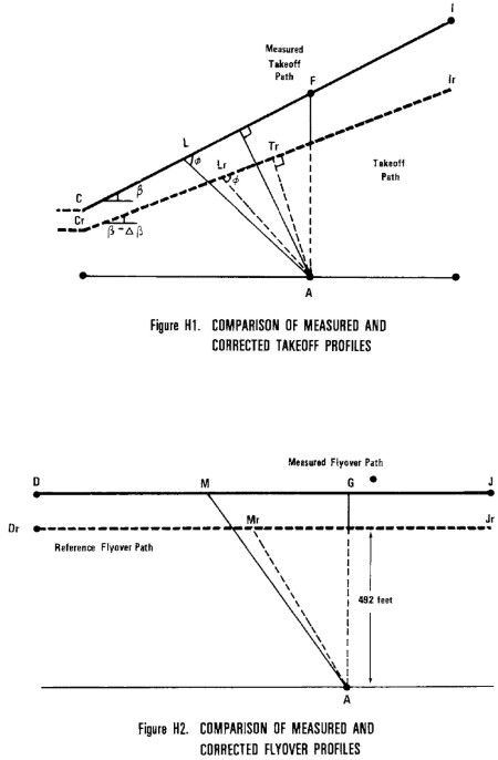
(2) Figure H2 illustrates comparative flyover profiles when test
conditions do not conform to prescribed reference conditions. The position
of the helicopter shall be recorded for a distance (DJ) sufficient to
ensure recording of the entire interval during which the measured
helicopter noise level is within 10 dB of PNLTM, as required. The flyover
profile is defined by the height AG which is a function of the operating
conditions controlled by the pilot. Position M represents the helicopter
location on the measured flyover flight path for which PNLTM is observed
at station A, and Mr is the corresponding position on the
reference flight path.
(d) Approach profiles. (1) Figure H3 illustrates a typical
approach profile, including reference conditions.
(2) The helicopter approaches position H along a 6° (±0.5°) average
approach slope throughout the 10 dB down period. The approach procedure
shall be acceptable to the FAA and shall be included in the Flight Manual.
(3) Figure H3 illustrates portions of the measured and reference
approach flight paths including the significant geometrical relationships
influencing sound propagation. EK represents the measured approach path
with approach angle η, and Er and Kr represent the
reference approach angle of 6°. Position N represents the helicopter
location on the measured approach flight path for which PNLTM is observed
at station A, and Nr is the corresponding position on the
reference approach flight path. The measured and corrected noise
propagation paths are AN and ANr, respectively, both of which
form the same angle with their flight paths. Position S represents the
point on the measured approach flight path nearest station A, and Sr
is the corresponding point on the reference approach flight path. The
minimum distance to the measured and reference flight paths are indicated
by the lines AS and ASr, respectively, which are normal to
their flight paths.
(e) Correction of noise at source during level flyover. (1) For
level overflight, if any combination of the following three factors, 1)
airspeed deviation from reference, 2) rotor speed deviation from
reference, and 3) temperature deviation from reference, results in an
advancing blade tip Mach number which deviates from the reference Mach
value, then source noise adjustments shall be determined. This adjustment
shall be determined from the manufacturer supplied data approved by the
FAA.
(2) Off-reference tip Mach number adjustments shall be based upon a
sensitivity curve of PNLTM versus advancing blade tip Mach number, deduced
from overflights carried out at different airspeeds around the reference
airspeed. If the test aircraft is unable to attain the reference value,
then an extrapolation of the sensitivity curve is permitted if data cover
at least a range of 0.3 Mach units. The advancing blade tip Mach number
shall be computed using true airspeed, onboard outside air temperature,
and rotor speed. A separate PNLTM versus advancing blade tip Mach number
function shall be derived for each of the three certification microphone
locations, i.e., centerline, sideline left, and sideline right. Sideline
left and right are defined relative to the direction of the flight on each
run. PNLTM adjustments are to be applied to each microphone datum using
the appropriate PNLTM function.
(f) PNLT corrections. If the ambient atmospheric conditions of
temperature and relative humidity are not those prescribed as reference
conditions under this appendix (77 degrees F and 70 percent,
respectively), corrections to the EPNL values must be calculated from the
measured data under paragraph (a) of this section as follows:
(1) Takeoff flight path. For the takeoff flight path shown in
Figure H1, the spectrum of PNLTM observed at station A for the aircraft at
position Lr is decomposed into its individual SPLi values.
(i) Step 1. A set of corrected values are then computed as follows:
SPLic=SPLi+(α i−α io)AL
+(α io)AL−ALr)
+20 log(AL/ALr)
Where SPLi and SPLic are the measured and corrected sound pressure
levels, respectively, in the i-th one-third octave band. The first
correction term accounts for the effects of change in atmospheric sound
absorption where ai and aio are the sound absorption coefficients for the
test and reference atmospheric conditions, respectively, for the -ith
one-third octave band and Lr A is the measured takeoff sound
propagation path. The second correction term accounts for the effects of
atmospheric sound absorption on the change in the sound propagation path
length where Lr A is the corrected takeoff sound propagation
path. The third correction term accounts for the effects of the inverse
square law on the change in the sound propagation path length.
(ii) Step 2. The corrected values of the SPLic are then converted to
PNLT and a correction term calculated as follows:
Δ1=PNLT−PNLTM
Which represents the correction to be added algebraically to the EPNL
calculated from the measured data.
(2) Approach flight path. (i) The procedure described in
paragraph (f)(1) of this section for takeoff flight paths is also used for
the approach flight path, except that the value for SPLic relate to the
approach sound propagation paths shown in Figure H3 as follows:
SPLic=SPLi+(α-α io) AM+
α(AM−AMr)+20 log(AM/AMr)
Where the lines NS and Nr Sr are the measured
and referenced approach sound propagation paths, respectively.
(ii) The remainder of the procedure is the same as that prescribed in
paragraph (d)(1)(ii) of this section, regarding takeoff flight path.
(3) Sideline microphones. The procedure prescribed in paragraph
(f)(1) of this section for takeoff flight paths is also used for the
propagation to the sideline microphones, except that the values of SPLic
relate only in the measured sideline sound propagation path as follows:
SPLic-SPLi + (α io−α+io)KX
+α io(KX−KXr)+20 log(KX/KXr)
K is the sideline measuring station where
X=L and Xr=Ln for takeoff
X=M and Xr=Mn for approach
X=N and Xr=Nr for flyover
(4) Level flyover flight path. The procedure prescribed in
paragraph (f)(1) of this section for takeoff flight paths is also used for
the level flyover flight path, except that the values of SPLic relate only
to the flyover sound propagation paths as follows:
SPLic=SPLi+(α-α io) AN + α io (AN−ANr)+20 log (AN/ANr)
(g) Duration corrections. (1) If the measured takeoff and
approach flight paths do not conform to those prescribed as the corrected
and reference flight paths, respectively, under section A36.5(d)(2) it
will be necessary to apply duration corrections to the EPNL values
calculated from the measured data. Such corrections must be calculated as
follows:
(i) Takeoff flight path. For the takeoff flight path shown in
Figure H1, the correction term is calculated using the formula --
Δ2=−10 log (AT/ATr) + 10 log (V/Vr)
which represents the correction which must be added algebraically to
the EPNL calculated from the measured data. The lengths AT and ATr are the
measured and corrected takeoff minimum distances from the noise measuring
station A to the measured and the corrected flight paths, respectively. A
negative sign indicates that, for the particular case of a duration
correction, the EPNL calculated from the measured data must be reduced if
the measured flight path is at greater altitude than the corrected flight
path.
(ii) Approach flight path. For the approach flight path shown in
Figure H3, the correction term is calculated using the formula --
Δ2=−10 log (AS/ASr) + 10 log (V/Vr)
where AS is the measured approach minimum distance from the noise
measuring station A to the measured flight path and 394 feet is the
minimum distance from station A to the reference flight path.
(iii) Sideline microphones. For the sideline flight path, the
correction term is calculated using the formula --
Δ2=−10 log (KX/KXr)+10 log (V/Vr)
K is the sideline measuring station
where X=T and Xr=Tr for takeoff
where X=S and Xr=Sr for approach
where X=G and Xr=Gr for flyover
(iv) Level flyover flight paths. For the level flyover flight
path, the correction term is calculated using the formula --
Δ2=−10 log (AG/AGr)+10 log (V/Vr)
where AG is the measured flyover altitude over the noise measuring
station A.
(2) The adjustment procedure described in this section shall apply to
the sideline microphones in the take-off, overflight, and approach cases.
Although the noise emission is strongly dependent on the directivity
pattern, variable from one helicopter type to another, the propagation
angle &thetas; shall be the same for test and reference flight paths. The
elevation angle ψ shall not be constrained but must be determined and
reported. The certification authority shall specify the acceptable
limitations on ψ. Corrections to data obtained when these limits are
exceeded shall be applied using FAA approved procedures.
PART D -- NOISE LIMITS UNDER §36.805
Section H36.301 Noise measurement, evaluation, and calculation
Compliance with this part of this appendix must be shown with noise
levels measured, evaluated, and calculated as prescribed under Parts B and
C of this appendix.
Section H36.303 [RESERVED]
Section H36.305 Noise levels
(a) Limits. For compliance with this appendix, it must be shown
by flight test that the calculated noise levels of the helicopter, at the
measuring points described in section H36.305(a) of this appendix, do not
exceed the following, with appropriate interpolation between weights:
(1) Stage 1 noise limits for acoustical changes for helicopters
are as follows:
(i) For takeoff, flyover, and approach calculated noise levels, the
noise levels of each Stage 1 helicopter that exceed the Stage 2 noise
limits plus 2 EPNdB may not, after a change in type design, exceed the
noise levels created prior to the change in type design.
(ii) For takeoff, flyover, and approach calculated noise levels, the
noise levels of each Stage 1 helicopter that do not exceed the Stage 2
noise limits plus 2 EPNdB may not, after the change in type design, exceed
the Stage 2 noise limits plus 2 EPNdB.
(2) Stage 2 noise limits are as follows:
(i) For takeoff calculated noise levels -- 109 EPNdB for maximum
takeoff weights of 176,370 pounds or more, reduced by 3.01 EPNdB per
halving of the weight down to 89 EPNdB for maximum weights of 1,764 pounds
or less.
(ii) For flyover calculated noise levels -- 108 EPNdB for
maximum weights of 176,370 pounds or more, reduced by 3.01 EPNdB per
halving of the weight down to 88 EPNdB for maximum weights of 1,764 pounds
or less.
(iii) For approach calculated noise levels -- 110 EPNdB for
maximum weights of 176,370 pounds or more, reduced by 3.01 EPNdB per
halving of the weight down 90 EPNdB for maximum weight of 1,764 pounds or
less.
(b) Tradeoffs. Except to the extent limited under §36.11(b) of
this part, the noise limits prescribed in paragraph (a) of this section
may be exceeded by one or two of the takeoff, flyover, or approach
calculated noise levels determined under section H36.203 of this appendix
if
(1) The sum of the exceedances is not greater than 4 EPNdB;
(2) No exceedance is greater than 3 EPNdB; and
(3) The exceedances are completely offset by reduction in the other
required calculated noise levels.
[Amdt. 36-14, 53 FR 3541, Feb. 5, 1988; 53 FR 4099, Feb. 11,
1988; 53 FR 7728, Mar. 10, 1988, as amended by Amdt. 36-54, 67 FR 45237,
July 8, 2002]