|
5-3-1. ARTCC
Communications
a. Direct
Communications, Controllers and Pilots.
1.
ARTCC's are capable of direct
communications with IFR air traffic on certain
frequencies. Maximum communications coverage is possible
through the use of Remote Center Air/Ground (RCAG) sites
comprised of both VHF and UHF transmitters and
receivers. These sites are located throughout the U.S.
Although they may be several hundred miles away from the
ARTCC, they are remoted to the various ARTCC's by land
lines or microwave links. Since IFR operations are
expedited through the use of direct communications,
pilots are requested to use these frequencies strictly
for communications pertinent to the control of IFR
aircraft. Flight plan filing, en route weather, weather
forecasts, and similar data should be requested through
FSS's, company radio, or appropriate military facilities
capable of performing these services.
2.
An ARTCC is divided into sectors. Each
sector is handled by one or a team of controllers and
has its own sector discrete frequency. As a flight
progresses from one sector to another, the pilot is
requested to change to the appropriate sector discrete
frequency.
b. ATC Frequency Change
Procedures.
1.
The following phraseology will be used by
controllers to effect a frequency change:
EXAMPLE-
(Aircraft identification) contact (facility name or
location name and terminal function) (frequency) at
(time, fix, or altitude).
NOTE-
Pilots are expected to maintain a listening watch on the
transferring controller's frequency until the time, fix,
or altitude specified. ATC will omit frequency change
restrictions whenever pilot compliance is expected upon
receipt.
2.
The following phraseology should be
utilized by pilots for establishing contact with the
designated facility:
(a)
When operating in a radar environment:
On initial contact, the pilot should inform the
controller of the aircraft's assigned altitude
preceded by the words "level," or "climbing to," or
"descending to," as appropriate; and the aircraft's
present vacating altitude, if applicable.
EXAMPLE-
1. (Name) CENTER,
(aircraft identification), LEVEL (altitude or flight
level).
2. (Name) CENTER, (aircraft identification),
LEAVING (exact altitude or flight level), CLIMBING TO
OR DESCENDING TO (altitude of flight level).
NOTE-
Exact altitude or flight level means to the nearest
100 foot increment. Exact altitude or flight level
reports on initial contact provide ATC with
information required prior to using Mode C altitude
information for separation purposes.
(b)
When operating in a nonradar
environment:
(1)
On initial contact, the pilot should
inform the controller of the aircraft's present
position, altitude and time estimate for the next
reporting point.
EXAMPLE-
(Name) CENTER,
(aircraft identification), (position), (altitude),
ESTIMATING (reporting point) AT (time).
(2)
After initial contact, when a
position report will be made, the pilot should give
the controller a complete position report.
EXAMPLE-
(Name) CENTER,
(aircraft identification), (position), (time),
(altitude), (type of flight plan), (ETA and name of
next reporting point), (the name of the next
succeeding reporting point), AND (remarks).
REFERENCE-
AIM, Position Reporting, Paragraph 5-3-2.
3.
At times controllers will ask pilots to
verify that they are at a particular altitude. The
phraseology used will be: "VERIFY AT (altitude)." In
climbing or descending situations, controllers may ask
pilots to "VERIFY ASSIGNED ALTITUDE AS (altitude)."
Pilots should confirm that they are at the altitude
stated by the controller or that the assigned altitude
is correct as stated. If this is not the case, they
should inform the controller of the actual altitude
being maintained or the different assigned altitude.
CAUTION-
Pilots should not take action to change their actual
altitude or different assigned altitude to the altitude
stated in the controllers verification request unless
the controller specifically authorizes a change.
c. ARTCC Radio Frequency
Outage. ARTCC's normally have at
least one back-up radio receiver and transmitter system
for each frequency, which can usually be placed into
service quickly with little or no disruption of ATC
service. Occasionally, technical problems may cause a
delay but switchover seldom takes more than 60 seconds.
When it appears that the outage will not be quickly
remedied, the ARTCC will usually request a nearby
aircraft, if there is one, to switch to the affected
frequency to broadcast communications instructions. It is
important, therefore, that the pilot wait at least 1
minute before deciding that the ARTCC has actually
experienced a radio frequency failure. When such an outage
does occur, the pilot should, if workload and equipment
capability permit, maintain a listening watch on the
affected frequency while attempting to comply with the
following recommended communications procedures:
1.
If two-way communications cannot be
established with the ARTCC after changing frequencies, a
pilot should attempt to recontact the transferring
controller for the assignment of an alternative
frequency or other instructions.
2.
When an ARTCC radio frequency failure
occurs after two-way communications have been
established, the pilot should attempt to reestablish
contact with the center on any other known ARTCC
frequency, preferably that of the next responsible
sector when practicable, and ask for instructions.
However, when the next normal frequency change along the
route is known to involve another ATC facility, the
pilot should contact that facility, if feasible, for
instructions. If communications cannot be reestablished
by either method, the pilot is expected to request
communications instructions from the FSS appropriate to
the route of flight.
NOTE-
The exchange of information between an aircraft and an
ARTCC through an FSS is quicker than relay via company
radio because the FSS has direct interphone lines to the
responsible ARTCC sector. Accordingly, when
circumstances dictate a choice between the two, during
an ARTCC frequency outage, relay via FSS radio is
recommended.

5-3-2. Position
Reporting
The safety and effectiveness
of traffic control depends to a large extent on accurate
position reporting. In order to provide the proper
separation and expedite aircraft movements, ATC must be able
to make accurate estimates of the progress of every aircraft
operating on an IFR flight plan.
a. Position
Identification.
1.
When a position report is to be made
passing a VOR radio facility, the time reported should
be the time at which the first complete reversal of the
"to/from" indicator is accomplished.
2.
When a position report is made passing a
facility by means of an airborne ADF, the time reported
should be the time at which the indicator makes a
complete reversal.
3.
When an aural or a light panel indication
is used to determine the time passing a reporting point,
such as a fan marker, Z marker, cone of silence or
intersection of range courses, the time should be noted
when the signal is first received and again when it
ceases. The mean of these two times should then be taken
as the actual time over the fix.
4.
If a position is given with respect to
distance and direction from a reporting point, the
distance and direction should be computed as accurately
as possible.
5.
Except for terminal area transition
purposes, position reports or navigation with reference
to aids not established for use in the structure in
which flight is being conducted will not normally be
required by ATC.
b. Position Reporting
Points. CFR's require pilots to
maintain a listening watch on the appropriate frequency
and, unless operating under the provisions of subparagraph
c, to furnish position reports passing certain reporting
points. Reporting points are indicated by symbols on en
route charts. The designated compulsory reporting point
symbol is a solid triangle and the "on request" reporting
point symbol is the open triangle . Reports passing an "on
request" reporting point are only necessary when requested
by ATC.
c. Position
Reporting Requirements.
1. Flights along
airways or routes.
A position
report is required by all flights regardless of
altitude, including those operating in accordance with
an ATC clearance specifying "VFR-on-top," over
each designated compulsory reporting point along the
route being flown.
2. Flights Along a
Direct Route. Regardless of
the altitude or flight level being flown, including
flights operating in accordance with an ATC clearance
specifying "VFR-on-top," pilots shall report over
each reporting point used in the flight plan to define
the route of flight.
3. Flights in a Radar
Environment. When informed by
ATC that their aircraft are in "Radar Contact," pilots
should discontinue position reports over designated
reporting points. They should resume normal position
reporting when ATC advises "RADAR CONTACT LOST"
or "RADAR SERVICE TERMINATED."
NOTE-
ATC will inform pilots that they are in "radar contact":
(a) when their aircraft is initially identified
in the ATC system; and
(b) when radar identification is reestablished
after radar service has been terminated or radar contact
lost.
Subsequent to being advised that the controller has
established radar contact, this fact will not be
repeated to the pilot when handed off to another
controller. At times, the aircraft identity will be
confirmed by the receiving controller; however, this
should not be construed to mean that radar contact has
been lost. The identity of transponder equipped aircraft
will be confirmed by asking the pilot to "ident,"
"squawk standby," or to change codes. Aircraft without
transponders will be advised of their position to
confirm identity. In this case, the pilot is expected to
advise the controller if in disagreement with the
position given. Any pilot who cannot confirm the
accuracy of the position given because of not being
tuned to the NAVAID referenced by the controller, should
ask for another radar position relative to the tuned in
NAVAID.
d. Position Report
Items:
1. Position reports
should include the following items:
(a)
Identification;
(b)
Position;
(c)
Time;
(d)
Altitude or flight level (include
actual altitude or flight level when operating on a
clearance specifying VFR-on-top);
(e)
Type of flight plan (not required in
IFR position reports made directly to ARTCC's or
approach control);
(f)
ETA and name of next reporting point;
(g)
The name only of the next succeeding
reporting point along the route of flight; and
(h)
Pertinent remarks.
5-3-3. Additional
Reports
a. The following reports
should be made to ATC or FSS facilities without a specific
ATC request:
1. At all times.
(a)
When vacating any previously assigned
altitude or flight level for a newly assigned altitude
or flight level.
(b)
When an altitude change will be made if
operating on a clearance specifying VFR-on-top.
(c)
When unable to climb/descend at
a rate of a least 500 feet per minute.
(d)
When approach has been missed. (Request
clearance for specific action; i.e., to alternative
airport, another approach, etc.)
(e)
Change in the average true airspeed (at
cruising altitude) when it varies by 5 percent or 10
knots (whichever is greater) from that filed in the
flight plan.
(f)
The time and altitude or flight level
upon reaching a holding fix or point to which cleared.
(g)
When leaving any assigned holding
fix or point.
NOTE-
The reports in subparagraphs (f) and (g) may be
omitted by pilots of aircraft involved in instrument
training at military terminal area facilities when
radar service is being provided.
(h)
Any loss, in controlled airspace, of
VOR, TACAN, ADF, low frequency navigation receiver
capability, GPS anomalies while using installed IFR-certified
GPS/GNSS receivers, complete or partial loss of ILS
receiver capability or impairment of air/ground
communications capability. Reports should include
aircraft identification, equipment affected, degree to
which the capability to operate under IFR in the ATC
system is impaired, and the nature and extent of
assistance desired from ATC.
NOTE-
1. Other equipment
installed in an aircraft may effectively impair safety
and/or the ability to operate under IFR. If such
equipment (e.g. airborne weather radar) malfunctions
and in the pilot's judgment either safety or IFR
capabilities are affected, reports should be made as
above.
2. When reporting GPS anomalies, include
the location and altitude of the anomaly. Be specific
when describing the location and include duration of
the anomaly if necessary.
(i)
Any information relating to the safety
of flight.
2. When not in radar
contact.
(a)
When leaving final approach fix inbound
on final approach (nonprecision approach) or when
leaving the outer marker or fix used in lieu of the
outer marker inbound on final approach (precision
approach).
(b)
A corrected estimate at anytime it
becomes apparent that an estimate as previously
submitted is in error in excess of 3 minutes.
b.
Pilots encountering weather conditions
which have not been forecast, or hazardous conditions
which have been forecast, are expected to forward a report
of such weather to ATC.
REFERENCE-
AIM, Pilot Weather Reports (PIREP's), Paragraph 7-1-19.
14 CFR Section 91.183(B) and (C).
5-3-4.
Airways and Route Systems
a.
Two fixed route systems are established for
air navigation purposes. They are the VOR and L/MF system,
and the jet route system. To the extent possible, these
route systems are aligned in an overlying manner to
facilitate transition between each.
1.
The VOR and L/MF Airway System consists
of airways designated from 1,200 feet above the surface
(or in some instances higher) up to but not including
18,000 feet MSL. These airways are depicted on Enroute
Low Altitude Charts.
NOTE-
The altitude limits of a victor airway should not be
exceeded except to effect transition within or between
route structures.
(a)
Except in Alaska and coastal North
Carolina, the VOR airways are predicated solely on VOR
or VORTAC navigation aids; are depicted in blue on
aeronautical charts; and are identified by a "V"
(Victor) followed by the airway number (e.g., V12).
NOTE-
Segments of VOR airways in Alaska and North Carolina
(V56, V290) are based on L/MF navigation aids and
charted in brown instead of blue on en route charts.
(1)
A segment of an airway which is
common to two or more routes carries the numbers of
all the airways which coincide for that segment.
When such is the case, pilots filing a flight plan
need to indicate only that airway number for the
route filed.
NOTE-
A pilot who intends to make an airway flight, using
VOR facilities, will simply specify the appropriate
"victor" airways(s) in the flight plan. For example,
if a flight is to be made from Chicago to New
Orleans at 8,000 feet, using omniranges only, the
route may be indicated as "departing from
Chicago-Midway, cruising 8,000 feet via Victor 9 to
Moisant International." If flight is to be conducted
in part by means of L/MF navigation aids and in part
on omniranges, specifications of the appropriate
airways in the flight plan will indicate which types
of facilities will be used along the described
routes, and, for IFR flight, permit ATC to issue a
traffic clearance accordingly. A route may also be
described by specifying the station over which the
flight will pass, but in this case since many VOR's
and L/MF aids have the same name, the pilot must be
careful to indicate which aid will be used at a
particular location. This will be indicated in the
route of flight portion of the flight plan by
specifying the type of facility to be used after the
location name in the following manner: Newark L/MF,
Allentown VOR.
(2)
With respect to position reporting,
reporting points are designated for VOR Airway
Systems. Flights using Victor Airways will report
over these points unless advised otherwise by ATC.
(b)
The L/MF airways (colored airways) are
predicated solely on L/MF navigation aids and are
depicted in brown on aeronautical charts and are
identified by color name and number (e.g., Amber One).
Green and Red airways are plotted east and west. Amber
and Blue airways are plotted north and south.
NOTE-
Except for G13 in North Carolina, the colored airway
system exists only in the state of Alaska. All other
such airways formerly so designated in the
conterminous U.S. have been rescinded.
2.
The jet route system consists of jet
routes established from 18,000 feet MSL to FL 450
inclusive.
(a)
These routes are depicted on Enroute
High Altitude Charts. Jet routes are depicted in black
on aeronautical charts and are identified by a "J"
(Jet) followed by the airway number (e.g., J12). Jet
routes, as VOR airways, are predicated solely on VOR
or VORTAC navigation facilities (except in Alaska).
NOTE-
Segments of jet routes in Alaska are based on L/MF
navigation aids and are charted in brown color instead
of black on en route charts.
(b)
With respect to position reporting,
reporting points are designated for jet route systems.
Flights using jet routes will report over these points
unless otherwise advised by ATC.
3. Area Navigation (RNAV)
Routes.
(a)
RNAV is a method of navigation that
permits aircraft operations on any desired course
within the coverage of station referenced navigation
signals or within the limits of a self-contained
system capability or combination of these.
(b)
Fixed RNAV routes are permanent,
published routes which can be flight planned for use
by aircraft with RNAV capability. A previously
established fixed RNAV route system has been
terminated except for a few high altitude routes in
Alaska.
(c)
Random RNAV routes are direct routes,
based on area navigation capability, between waypoints
defined in terms of latitude/longitude coordinates,
degree-distance fixes, or offsets from established
routes/airways at a specified distance and direction.
Radar monitoring by ATC is required on all random RNAV
routes.
b.
Operation above FL 450 may be conducted on
a point-to-point basis. Navigational guidance is provided
on an area basis utilizing those facilities depicted on
the enroute high altitude charts.
c. Radar Vectors.
Controllers may vector aircraft within
controlled airspace for separation purposes, noise
abatement considerations, when an operational advantage
will be realized by the pilot or the controller, or when
requested by the pilot. Vectors outside of controlled
airspace will be provided only on pilot request. Pilots
will be advised as to what the vector is to achieve when
the vector is controller initiated and will take the
aircraft off a previously assigned nonradar route. To the
extent possible, aircraft operating on RNAV routes will be
allowed to remain on their own navigation.
d.
When flying in Canadian airspace, pilots
are cautioned to review Canadian Air Regulations.
1.
Special attention should be given to the
parts which differ from U.S. CFR's.
(a)
The Canadian Airways Class B airspace
restriction is an example. Class B airspace is all
controlled low level airspace above 12,500 feet MSL or
the MEA, whichever is higher, within which only IFR
and controlled VFR flights are permitted. (Low level
airspace means an airspace designated and defined as
such in the Designated Airspace Handbook.)
(b)
Regardless of the weather conditions or
the height of the terrain, no person shall operate an
aircraft under VFR conditions within Class B airspace
except in accordance with a clearance for VFR flight
issued by ATC.
(c)
The requirement for entry into Class B
airspace is a student pilot permit (under the guidance
or control of a flight instructor).
(d)
VFR flight requires visual contact with
the ground or water at all times.
2.
Segments of VOR airways and high level
routes in Canada are based on L/MF navigation aids and
are charted in brown color instead of blue on en route
charts.
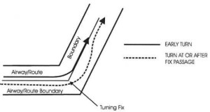
FIG 5-3-1
Adhering to Airways or
Routes
5-3-5.
Airway or Route Course Changes
a.
Pilots of aircraft are required to adhere
to airways or routes being flown. Special attention must
be given to this requirement during course changes. Each
course change consists of variables that make the
technique applicable in each case a matter only the pilot
can resolve. Some variables which must be considered are
turn radius, wind effect, airspeed, degree of turn, and
cockpit instrumentation. An early turn, as illustrated
below, is one method of adhering to airways or routes. The
use of any available cockpit instrumentation, such as
Distance Measuring Equipment, may be used by the pilot to
lead the turn when making course changes. This is
consistent with the intent of 14 CFR Section 91.181,
which requires pilots to operate along the centerline of
an airway and along the direct course between navigational
aids or fixes.
b.
Turns which begin at or after fix passage
may exceed airway or route boundaries. FIG 5-3-1 contains
an example flight track depicting this, together with an
example of an early turn.
c.
Without such actions as leading a turn,
aircraft operating in excess of 290 knots true air speed
(TAS) can exceed the normal airway or route boundaries
depending on the amount of course change required, wind
direction and velocity, the character of the turn fix (DME,
overhead navigation aid, or intersection), and the pilot's
technique in making a course change. For example, a flight
operating at 17,000 feet MSL with a TAS of 400 knots, a 25
degree bank, and a course change of more than 40 degrees
would exceed the width of the airway or route; i.e., 4
nautical miles each side of centerline. However, in the
airspace below 18,000 feet MSL, operations in excess of
290 knots TAS are not prevalent and the provision of
additional IFR separation in all course change situations
for the occasional aircraft making a turn in excess of 290
knots TAS creates an unacceptable waste of airspace and
imposes a penalty upon the preponderance of traffic which
operate at low speeds. Consequently, the FAA expects
pilots to lead turns and take other actions they consider
necessary during course changes to adhere as closely as
possible to the airways or route being flown.
d.
Due to the high airspeeds used at 18,000
feet MSL and above, FAA provides additional IFR separation
protection for course changes made at such altitude
levels.
5-3-6.
Changeover Points (COP's)
a.
COP's are prescribed for Federal airways,
jet routes, area navigation routes, or other direct routes
for which an MEA is designated under 14 CFR Part 95. The
COP is a point along the route or airway segment between
two adjacent navigation facilities or waypoints where
changeover in navigation guidance should occur. At this
point, the pilot should change navigation receiver
frequency from the station behind the aircraft to the
station ahead.
b.
The COP is normally located midway between
the navigation facilities for straight route segments, or
at the intersection of radials or courses forming a dogleg
in the case of dogleg route segments. When the COP is NOT
located at the midway point, aeronautical charts will
depict the COP location and give the mileage to the radio
aids.
c.
COP's are established for the purpose of
preventing loss of navigation guidance, to prevent
frequency interference from other facilities, and to
prevent use of different facilities by different aircraft
in the same airspace. Pilots are urged to observe COP's to
the fullest extent.
5-3-7. Holding
a.
Whenever an aircraft is cleared to a fix
other than the destination airport and delay is expected,
it is the responsibility of the ATC controller to issue
complete holding instructions (unless the pattern is
charted), an EFC time and best estimate of any additional
en route/terminal delay.
NOTE-
Only those holding patterns depicted on U.S. government or
commercially produced (meeting FAA requirements) low/high
altitude enroute, and area or STAR charts should be used.
b.
If the holding pattern is charted and the
controller doesn't issue complete holding instructions,
the pilot is expected to hold as depicted on the
appropriate chart. When the pattern is charted, the
controller may omit all holding instructions except the
charted holding direction and the statement AS
PUBLISHED; e.g., HOLD EAST AS PUBLISHED.
Controllers shall always issue complete holding
instructions when pilots request them.
c.
If no holding pattern is charted and
holding instructions have not been issued, the pilot
should ask ATC for holding instructions prior to reaching
the fix. This procedure will eliminate the possibility of
an aircraft entering a holding pattern other than that
desired by ATC. If unable to obtain holding instructions
prior to reaching the fix (due to frequency congestion,
stuck microphone, etc.), then enter a standard pattern on
the course on which the aircraft approached the fix and
request further clearance as soon as possible. In this
event, the altitude/flight level of the aircraft at the
clearance limit will be protected so that separation will
be provided as required.
d.
When an aircraft is 3 minutes or less from
a clearance limit and a clearance beyond the fix has not
been received, the pilot is expected to start a speed
reduction so that the aircraft will cross the fix,
initially, at or below the maximum holding airspeed.
e.
When no delay is expected, the controller
should issue a clearance beyond the fix as soon as
possible and, whenever possible, at least 5 minutes before
the aircraft reaches the clearance limit.
f.
Pilots should report to ATC the time and
altitude/flight level at which the aircraft reaches the
clearance limit and report leaving the clearance limit.
NOTE-
In the event of two-way communications failure, pilots are
required to comply with 14 CFR Section 91.185.
g.
When holding at a VOR station, pilots
should begin the turn to the outbound leg at the time of
the first complete reversal of the to/from indicator.
h.
Patterns at the most generally used holding
fixes are depicted (charted) on U.S. Government or
commercially produced (meeting FAA requirements) Low or
High Altitude Enroute, Area and STAR Charts. Pilots are
expected to hold in the pattern depicted unless
specifically advised otherwise by ATC.
NOTE-
Holding patterns that protect for a maximum holding
airspeed other than the standard may be depicted by an
icon, unless otherwise depicted. The icon is a standard
holding pattern symbol (racetrack) with the airspeed
restriction shown in the center. In other cases, the
airspeed restriction will be depicted next to the standard
holding pattern symbol.
REFERENCE-
AIM, Holding, Paragraph 5-3-7j2.
i.
An ATC clearance requiring an aircraft to
hold at a fix where the pattern is not charted will
include the following information: (See FIG 5-3-2.)
1.
Direction of holding from the fix in
terms of the eight cardinal compass points (i.e., N, NE,
E, SE, etc.).
2.
Holding fix (the fix may be omitted if
included at the beginning of the transmission as the
clearance limit).
3.
Radial, course, bearing, airway or route
on which the aircraft is to hold.
4.
Leg length in miles if DME or RNAV is to
be used (leg length will be specified in minutes on
pilot request or if the controller considers it
necessary).
5.
Direction of turn if left turns are to be
made, the pilot requests, or the controller considers it
necessary.
6.
Time to expect further clearance and any
pertinent additional delay information.
FIG 5-3-2
Holding Patterns
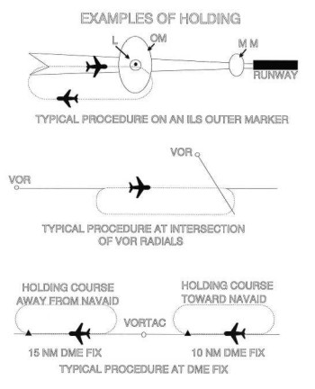
FIG 5-3-3
Holding Pattern
Descriptive Terms
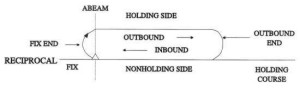
j.
Holding pattern airspace
protection is based on the following procedures.
1. Descriptive Terms.
(a) Standard
Pattern. Right turns
(See FIG 5-3-3.)
(b) Nonstandard
Pattern. Left turns
2. Airspeeds.
(a)
All aircraft may hold at the following
altitudes and maximum holding airspeeds:
TBL 5-3-1
|
Altitude (MSL)
|
Airspeed (KIAS)
|
|
MHA - 6,000'
|
200 |
|
6,001' - 14,000'
|
230 |
|
14,001' and above
|
265 |
(b)
The following are exceptions to the
maximum holding airspeeds:
(1)
Holding patterns from 6,001' to
14,000' may be restricted to a maximum airspeed of
210 KIAS. This nonstandard pattern will be depicted
by an icon.
(2)
Holding patterns may be
restricted to a maximum airspeed of 175 KIAS. This
nonstandard pattern will be depicted by an icon.
Holding patterns restricted to 175 KIAS will
generally be found on instrument approach procedures
applicable to Category A and B aircraft only.
(3)
Holding patterns at USAF airfields
only - 310 KIAS maximum, unless otherwise depicted.
(4)
Holding patterns at Navy fields only
- 230 KIAS maximum, unless otherwise depicted.
(5)
When a climb-in hold is specified by
a published procedure (e.g., "Climb-in
holding pattern to depart XYZ VORTAC at or above
10,000." or "All aircraft climb-in TRUCK holding
pattern to cross TRUCK Int at or above 11,500 before
proceeding on course."), additional obstacle
protection area has been provided to allow for
greater airspeeds in the climb for those aircraft
requiring them. The holding pattern template for a
maximum airspeed of 310 KIAS has been used for the
holding pattern if there are no airspeed
restrictions on the holding pattern as specified in
subparagraph j2(b)(2) of this paragraph. Where the
holding pattern is restricted to a maximum airspeed
of 175 KIAS, the 200 KIAS holding pattern template
has been applied for published climb-in hold
procedures for altitudes 6,000 feet and below and
the 230 KIAS holding pattern template has been
applied for altitudes above 6,000 feet. The airspeed
limitations in 14 CFR Section 91.117, Aircraft
Speed, still apply.
(c)
The following phraseology may be used
by an ATCS to advise a pilot of the maximum holding
airspeed for a holding pattern airspace area.
PHRASEOLOGY-
(AIRCRAFT IDENTIFICATION) (holding instructions, when
needed) MAXIMUM HOLDING AIRSPEED IS (speed in knots).
FIG 5-3-4
Holding Pattern Entry
Procedures
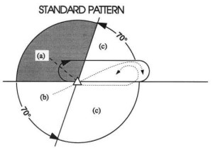
3. Entry Procedures.
(See FIG
5-3-4.)
(a) Parallel
Procedure. When approaching
the holding fix from anywhere in sector (a), the
parallel entry procedure would be to turn to a heading
to parallel the holding course outbound on the
nonholding side for one minute, turn in the direction
of the holding pattern through more than 180 degrees,
and return to the holding fix or intercept the holding
course inbound.
(b) Teardrop
Procedure. When approaching
the holding fix from anywhere in sector (b), the
teardrop entry procedure would be to fly to the fix,
turn outbound to a heading for a 30 degree teardrop
entry within the pattern (on the holding side) for a
period of one minute, then turn in the direction of
the holding pattern to intercept the inbound holding
course.
(c) Direct Entry
Procedure. When approaching
the holding fix from anywhere in sector (c), the
direct entry procedure would be to fly directly to the
fix and turn to follow the holding pattern.
(d)
While other entry procedures may enable
the aircraft to enter the holding pattern and remain
within protected airspace, the parallel, teardrop and
direct entries are the procedures for entry and
holding recommended by the FAA.
4. Timing.
(a) Inbound Leg.
(1)
At or below 14,000 feet MSL: 1
minute.
(2)
Above 14,000 feet MSL: 11/2
minutes.
NOTE-
The initial outbound leg should be flown for 1
minute or 1 1/2 minutes
(appropriate to altitude). Timing for subsequent
outbound legs should be adjusted, as necessary, to
achieve proper inbound leg time. Pilots may use any
navigational means available; i.e. DME, RNAV, etc.,
to insure the appropriate inbound leg times.
(b) Outbound leg
timing begins over/abeam the fix, whichever
occurs later. If the abeam position cannot be
determined, start timing when turn to outbound is
completed.
5. Distance Measuring
Equipment (DME). DME
holding is subject to the same entry and holding
procedures except that distances (nautical miles) are
used in lieu of time values. The outbound course
of a DME holding pattern is called the outbound leg of
the pattern. The length of the outbound leg will be
specified by the controller. The end of the outbound leg
is determined by the odometer reading.
(See FIG 5-3-5 and FIG 5-3-6.)
FIG 5-3-5
Inbound Leg Toward
NAVAID
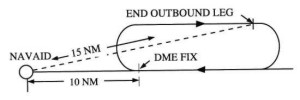
NOTE-
When the inbound course is toward the NAVAID and the fix
distance is 10 NM, and the leg length is 5 NM, then the
end of the outbound leg will be reached when the DME
reads 15 NM.
FIG 5-3-6
Inbound Leg Away from
NAVAID
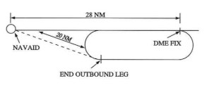
NOTE-
When the inbound course is away from the NAVAID and the
fix distance is 28 NM, and the leg length is 8 NM, then
the end of the outbound leg will be reached when the DME
reads 20 NM.
6. Pilot Action.
(a)
Start speed reduction when 3 minutes or
less from the holding fix. Cross the holding fix,
initially, at or below the maximum holding airspeed.
(b) Make all turns
during entry and while holding at:
(1)
3 degrees per second; or
(2)
30 degree bank angle; or
(3)
25 degree bank provided a flight
director system is used.
NOTE-
Use whichever requires the least bank angle.
(c)
Compensate for wind effect primarily by
drift correction on the inbound and outbound legs.
When outbound, triple the inbound drift correction to
avoid major turning adjustments; e.g., if correcting
left by 8 degrees when inbound, correct right by 24
degrees when outbound.
(d)
Determine entry turn from aircraft
heading upon arrival at the holding fix; +/-5
degrees in heading is considered to be within
allowable good operating limits for determining entry.
(e)
Advise ATC immediately what increased
airspeed is necessary, if any, due to turbulence,
icing, etc., or if unable to accomplish any part of
the holding procedures. When such higher speeds become
no longer necessary, operate according to the
appropriate published holding speed and notify ATC.
7. Nonstandard Holding
Pattern. Fix end and outbound
end turns are made to the left. Entry procedures to a
nonstandard pattern are oriented in relation to the 70
degree line on the holding side just as in the standard
pattern.
k.
When holding at a fix and instructions are
received specifying the time of departure from the fix,
the pilot should adjust the aircraft's flight path within
the limits of the established holding pattern in order to
leave the fix at the exact time specified. After departing
the holding fix, normal speed is to be resumed with
respect to other governing speed requirements, such as
terminal area speed limits, specific ATC requests, etc.
Where the fix is associated with an instrument approach
and timed approaches are in effect, a procedure turn shall
not be executed unless the pilot advises ATC, since
aircraft holding are expected to proceed inbound on final
approach directly from the holding pattern when approach
clearance is received.
l.
Radar surveillance of outer fix holding
pattern airspace areas.
1.
Whenever aircraft are holding at an outer
fix, ATC will usually provide radar surveillance of the
outer fix holding pattern airspace area, or any portion
of it, if it is shown on the controller's radar scope.
2.
The controller will attempt to detect any
holding aircraft that stray outside the holding pattern
airspace area and will assist any detected aircraft to
return to the assigned airspace area.
NOTE-
Many factors could prevent ATC from providing this
additional service, such as workload, number of targets,
precipitation, ground clutter, and radar system
capability. These circumstances may make it unfeasible
to maintain radar identification of aircraft to detect
aircraft straying from the holding pattern. The
provision of this service depends entirely upon whether
controllers believe they are in a position to provide it
and does not relieve a pilot of their responsibility to
adhere to an accepted ATC clearance.
3.
If an aircraft is established in a
published holding pattern at an assigned altitude above
the published minimum holding altitude and subsequently
cleared for the approach, the pilot may descend to the
published minimum holding altitude. The holding pattern
would only be a segment of the IAP if it is
published on the instrument procedure chart and is used
in lieu of a procedure turn.
m.
For those holding patterns where there are
no published minimum holding altitudes, the pilot, upon
receiving an approach clearance, must maintain the last
assigned altitude until leaving the holding pattern and
established on the inbound course. Thereafter, the
published minimum altitude of the route segment being
flown will apply. It is expected that the pilot will be
assigned a holding altitude that will permit a normal
descent on the inbound course.

|