|
1-1-1. General
a.
Various types of air
navigation aids are in use today, each serving a
special purpose. These aids have varied owners and
operators, namely: the Federal Aviation
Administration (FAA), the military services, private
organizations, individual states and foreign
governments. The FAA has the statutory authority to
establish, operate, maintain air navigation
facilities and to prescribe standards for the
operation of any of these aids which are used for
instrument flight in federally controlled airspace.
These aids are tabulated in the Airport/Facility
Directory (A/FD).
b.
Pilots should be aware
of the possibility of momentary erroneous
indications on cockpit displays when the primary
signal generator for a ground-based navigational
transmitter (for example, a glideslope, VOR, or
nondirectional beacon) is inoperative. Pilots should
disregard any navigation indication, regardless of
its apparent validity, if the particular transmitter
was identified by NOTAM or otherwise as unusable or
inoperative.

1-1-2.
Nondirectional Radio Beacon (NDB)
a.
A low or medium
frequency radio beacon transmits nondirectional
signals whereby the pilot of an aircraft properly
equipped can determine bearings and "home" on the
station. These facilities normally operate in the
frequency band of 190 to 535 kilohertz (kHz) and
transmit a continuous carrier with either 400 or
1020 hertz (Hz) modulation. All radio beacons except
the compass locators transmit a continuous
three-letter identification in code except during
voice transmissions.
b.
When a radio beacon is
used in conjunction with the Instrument Landing
System markers, it is called a Compass Locator.
c.
Voice transmissions are
made on radio beacons unless the letter "W" (without
voice) is included in the class designator (HW).
d.
Radio beacons are
subject to disturbances that may result in erroneous
bearing information. Such disturbances result from
such factors as lightning, precipitation static,
etc. At night, radio beacons are vulnerable to
interference from distant stations. Nearly all
disturbances which affect the Automatic Direction
Finder (ADF) bearing also affect the facility's
identification. Noisy identification usually occurs
when the ADF needle is erratic. Voice, music or
erroneous identification may be heard when a steady
false bearing is being displayed. Since ADF
receivers do not have a "flag" to warn the pilot
when erroneous bearing information is being
displayed, the pilot should continuously monitor the
NDB's identification.
1-1-3. VHF
Omni-directional Range (VOR)
a.
VOR's operate within
the 108.0 to 117.95 MHz frequency band and have a
power output necessary to provide coverage within
their assigned operational service volume. They are
subject to line-of-sight restrictions, and the range
varies proportionally to the altitude of the
receiving equipment.
NOTE-
Normal service ranges for the various classes of
VOR's are given in Navigational Aid (NAVAID) Service
Volumes, paragraph
1-1-8.
b.
Most VOR's are equipped
for voice transmission on the VOR frequency. VOR's
without voice capability are indicated by the letter
"W" (without voice) included in the class designator
(VORW).
c.
The only positive
method of identifying a VOR is by its Morse Code
identification or by the recorded automatic voice
identification which is always indicated by use of
the word "VOR" following the range's name. Reliance
on determining the identification of an omnirange
should never be placed on listening to voice
transmissions by the Flight Service Station (FSS)
(or approach control facility) involved. Many FSS's
remotely operate several omniranges with different
names. In some cases, none of the VOR's have the
name of the "parent" FSS. During periods of
maintenance, the facility may radiate a T-E-S-T code
(-
l l
l l
-)
or the code may be removed.
d.
Voice identification
has been added to numerous VOR's. The transmission
consists of a voice announcement, "AIRVILLE VOR"
alternating with the usual Morse Code
identification.
e.
The effectiveness of
the VOR depends upon proper use and adjustment of
both ground and airborne equipment.
1.
Accuracy.
The
accuracy of course alignment of the VOR is
excellent, being generally plus or minus 1 degree.
2.
Roughness.
On some
VOR's, minor course roughness may be observed,
evidenced by course needle or brief flag alarm
activity (some receivers are more susceptible to
these irregularities than others). At a few
stations, usually in mountainous terrain, the
pilot may occasionally observe a brief course
needle oscillation, similar to the indication of
"approaching station." Pilots flying over
unfamiliar routes are cautioned to be on the alert
for these vagaries, and in particular, to use the
"to/from" indicator to determine positive station
passage.
(a)
Certain
propeller revolutions per minute (RPM) settings
or helicopter rotor speeds can cause the VOR
Course Deviation Indicator to fluctuate as much
as plus or minus six degrees. Slight changes to
the RPM setting will normally smooth out this
roughness. Pilots are urged to check for this
modulation phenomenon prior to reporting a VOR
station or aircraft equipment for unsatisfactory
operation.
1-1-4. VOR
Receiver Check
a.
The FAA VOR test
facility (VOT) transmits a test signal which
provides users a convenient means to determine the
operational status and accuracy of a VOR receiver
while on the ground where a VOT is located. The
airborne use of VOT is permitted; however, its use
is strictly limited to those areas/altitudes
specifically authorized in the A/FD or appropriate
supplement.
b.
To use the VOT service,
tune in the VOT frequency on your VOR receiver. With
the Course Deviation Indicator (CDI) centered, the
omni-bearing selector should read 0 degrees with the
to/from indication showing "from" or the
omni-bearing selector should read 180 degrees with
the to/from indication showing "to." Should the VOR
receiver operate an RMI (Radio Magnetic Indicator),
it will indicate 180 degrees on any omni-bearing
selector (OBS) setting. Two means of identification
are used. One is a series of dots and the other is a
continuous tone. Information concerning an
individual test signal can be obtained from the
local FSS.
c.
Periodic VOR receiver
calibration is most important. If a receiver's
Automatic Gain Control or modulation circuit
deteriorates, it is possible for it to display
acceptable accuracy and sensitivity close into the
VOR or VOT and display out-of-tolerance readings
when located at greater distances where weaker
signal areas exist. The likelihood of this
deterioration varies between receivers, and is
generally considered a function of time. The best
assurance of having an accurate receiver is periodic
calibration. Yearly intervals are recommended at
which time an authorized repair facility should
recalibrate the receiver to the manufacturer's
specifications.
d.
Federal Aviation
Regulations (14 CFR Section 91.171) provides for
certain VOR equipment accuracy checks prior to
flight under instrument flight rules. To comply with
this requirement and to ensure satisfactory
operation of the airborne system, the FAA has
provided pilots with the following means of checking
VOR receiver accuracy:
1.
VOT or a radiated
test signal from an appropriately rated radio
repair station.
2.
Certified airborne
check points.
3.
Certified check
points on the airport surface.
e.
A radiated VOT from an
appropriately rated radio repair station serves the
same purpose as an FAA VOR signal and the check is
made in much the same manner as a VOT with the
following differences:
1.
The frequency
normally approved by the Federal Communications
Commission is 108.0 MHz.
2.
Repair stations are
not permitted to radiate the VOR test signal
continuously; consequently, the owner or operator
must make arrangements with the repair station to
have the test signal transmitted. This service is
not provided by all radio repair stations. The
aircraft owner or operator must determine which
repair station in the local area provides this
service. A representative of the repair station
must make an entry into the aircraft logbook or
other permanent record certifying to the radial
accuracy and the date of transmission. The owner,
operator or representative of the repair station
may accomplish the necessary checks in the
aircraft and make a logbook entry stating the
results. It is necessary to verify which test
radial is being transmitted and whether you should
get a "to" or "from" indication.
f.
Airborne and ground
check points consist of certified radials that
should be received at specific points on the airport
surface or over specific landmarks while airborne in
the immediate vicinity of the airport.
1.
Should an error in
excess of plus or minus 4 degrees be indicated
through use of a ground check, or plus or minus 6
degrees using the airborne check, Instrument
Flight Rules (IFR) flight shall not be attempted
without first correcting the source of the error.
CAUTION-
No correction other than the correction card
figures supplied by the manufacturer should be
applied in making these VOR receiver checks.
2.
Locations of airborne
check points, ground check points and VOT's are
published in the A/FD and are depicted on the A/G
voice communications panels on the FAA IFR area
chart and IFR enroute low altitude chart.
3.
If a dual system VOR
(units independent of each other except for the
antenna) is installed in the aircraft, one system
may be checked against the other. Turn both
systems to the same VOR ground facility and note
the indicated bearing to that station. The maximum
permissible variations between the two indicated
bearings is 4 degrees.
1-1-5.
Tactical Air Navigation (TACAN)
a.
For reasons peculiar to
military or naval operations (unusual siting
conditions, the pitching and rolling of a naval
vessel, etc.) the civil VOR/Distance Measuring
Equipment (DME) system of air navigation was
considered unsuitable for military or naval use. A
new navigational system, TACAN, was therefore
developed by the military and naval forces to more
readily lend itself to military and naval
requirements. As a result, the FAA has been in the
process of integrating TACAN facilities with the
civil VOR/DME program. Although the theoretical, or
technical principles of operation of TACAN equipment
are quite different from those of VOR/DME
facilities, the end result, as far as the navigating
pilot is concerned, is the same. These integrated
facilities are called VORTAC's.
b.
TACAN ground equipment
consists of either a fixed or mobile transmitting
unit. The airborne unit in conjunction with the
ground unit reduces the transmitted signal to a
visual presentation of both azimuth and distance
information. TACAN is a pulse system and operates in
the Ultrahigh Frequency (UHF) band of frequencies.
Its use requires TACAN airborne equipment and does
not operate through conventional VOR equipment.
1-1-6. VHF
Omni-directional Range/Tactical Air Navigation (VORTAC)
a.
A VORTAC is a facility
consisting of two components, VOR and TACAN, which
provides three individual services: VOR azimuth,
TACAN azimuth and TACAN distance (DME) at one site.
Although consisting of more than one component,
incorporating more than one operating frequency, and
using more than one antenna system, a VORTAC is
considered to be a unified navigational aid. Both
components of a VORTAC are envisioned as operating
simultaneously and providing the three services at
all times.
b.
Transmitted signals of
VOR and TACAN are each identified by three-letter
code transmission and are interlocked so that pilots
using VOR azimuth with TACAN distance can be assured
that both signals being received are definitely from
the same ground station. The frequency channels of
the VOR and the TACAN at each VORTAC facility are
"paired" in accordance with a national plan to
simplify airborne operation.
1-1-7.
Distance Measuring Equipment (DME)
a.
In the operation of DME,
paired pulses at a specific spacing are sent out
from the aircraft (this is the interrogation) and
are received at the ground station. The ground
station (transponder) then transmits paired pulses
back to the aircraft at the same pulse spacing but
on a different frequency. The time required for the
round trip of this signal exchange is measured in
the airborne DME unit and is translated into
distance (nautical miles) from the aircraft to the
ground station.
b.
Operating on the
line-of-sight principle, DME furnishes distance
information with a very high degree of accuracy.
Reliable signals may be received at distances up to
199 NM at line-of-sight altitude with an accuracy of
better than 1/2 mile or 3
percent of the distance, whichever is greater.
Distance information received from DME equipment is
SLANT RANGE distance and not actual horizontal
distance.
c.
DME operates on
frequencies in the UHF spectrum between 962 MHz and
1213 MHz. Aircraft equipped with TACAN equipment
will receive distance information from a VORTAC
automatically, while aircraft equipped with VOR must
have a separate DME airborne unit.
d.
VOR/DME, VORTAC,
Instrument Landing System (ILS)/DME, and localizer
(LOC)/DME navigation facilities established by the
FAA provide course and distance information from
collocated components under a frequency pairing
plan. Aircraft receiving equipment which provides
for automatic DME selection assures reception of
azimuth and distance information from a common
source when designated VOR/DME, VORTAC, ILS/DME, and
LOC/DME are selected.
e.
Due to the limited
number of available frequencies, assignment of
paired frequencies is required for certain military
noncollocated VOR and TACAN facilities which serve
the same area but which may be separated by
distances up to a few miles. The military is
presently undergoing a program to collocate VOR and
TACAN facilities or to assign nonpaired frequencies
to those that cannot be collocated.
f.
VOR/DME, VORTAC, ILS/DME,
and LOC/DME facilities are identified by
synchronized identifications which are transmitted
on a time share basis. The VOR or localizer portion
of the facility is identified by a coded tone
modulated at 1020 Hz or a combination of code and
voice. The TACAN or DME is identified by a coded
tone modulated at 1350 Hz. The DME or TACAN coded
identification is transmitted one time for each
three or four times that the VOR or localizer coded
identification is transmitted. When either the VOR
or the DME is inoperative, it is important to
recognize which identifier is retained for the
operative facility. A single coded identification
with a repetition interval of approximately 30
seconds indicates that the DME is operative.
g.
Aircraft equipment
which provides for automatic DME selection assures
reception of azimuth and distance information from a
common source when designated VOR/DME, VORTAC and
ILS/DME navigation facilities are selected. Pilots
are cautioned to disregard any distance displays
from automatically selected DME equipment when VOR
or ILS facilities, which do not have the DME feature
installed, are being used for position
determination.
1-1-8.
Navigational Aid (NAVAID) Service Volumes
a.
Most air navigation
radio aids which provide positive course guidance
have a designated standard service volume (SSV). The
SSV defines the reception limits of unrestricted
NAVAID's which are usable for random/unpublished
route navigation.
b.
A NAVAID will be
classified as restricted if it does not conform to
flight inspection signal strength and course quality
standards throughout the published SSV. However, the
NAVAID should not be considered usable at altitudes
below that which could be flown while operating
under random route IFR conditions (14 CFR Section
91.177), even though these altitudes may lie within
the designated SSV. Service volume restrictions are
first published in Notices to Airmen (NOTAM's) and
then with the alphabetical listing of the NAVAID's
in the A/FD.
c.
Standard Service Volume
limitations do not apply to published IFR routes or
procedures.
d.
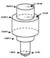
VOR/DME/TACAN Standard
Service Volumes (SSV).
1.
Standard service
volumes (SSV's) are graphically shown in FIG
1-1-1, FIG 1-1-2, FIG 1-1-3,
FIG 1-1-4, and
1-1-5. The SSV of a station
is indicated by using the class designator as a
prefix to the station type designation.
EXAMPLE-
TVOR, LDME, and HVORTAC.
FIG 1-1-1
Standard High Altitude Service Volume
(See
FIG 1-1-5
for altitudes below 1,000 feet).
click on image to
enlarge
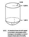
FIG 1-1-2
Standard Low Altitude Service Volume
(See
FIG 1-1-5
for altitudes below 1,000 feet).
click on image to
enlarge
FIG 1-1-3
Standard Terminal Service Volume
(See
FIG 1-1-4
for altitudes below 1,000 feet).

click on image to
enlarge
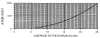
2.
Within 25 NM, the
bottom of the T service volume is defined by the
curve in
FIG 1-1-4. Within 40 NM,
the bottoms of the L and H service volumes are
defined by the curve in
FIG 1-1-5. (See TBL 1-1-1.)
TBL 1-1-1
VOR/DME/TACAN
Standard Service Volumes
|
SSV Class Designator |
Altitude and Range Boundaries |
|
T
(Terminal)
|
From 1,000 feet above ground level (AGL) up to
and including 12,000 feet AGL at radial
distances out to 25 NM. |
|
L
(Low Altitude)
|
From 1,000 feet AGL up to and including 18,000
feet AGL at radial distances out to 40 NM. |
|
H
(High Altitude)
|
From 1,000 feet AGL up to and including 14,500
feet AGL at radial distances out to 40 NM. From
14,500 AGL up to and including 60,000 feet at
radial distances out to 100 NM. From 18,000 feet
AGL up to and including 45,000 feet AGL at
radial distances out to 130 NM. |
e.
Nondirectional Radio Beacon (NDB)
1.
NDB's are classified
according to their intended use.
2.
The ranges of NDB
service volumes are shown in TBL 1-1-2. The
distances (radius) are the same at all altitudes.
TBL 1-1-2
NDB
Service Volumes
|
Class |
Distance
(Radius) |
|
Compass Locator |
15 NM
|
|
MH
|
25 NM
|
|
H
|
50 NM*
|
|
HH
|
75 NM
|
|
* Service ranges of individual facilities may
be less than 50 nautical miles (NM).
Restrictions to service volumes are first
published as a Notice to Airmen and then with
the alphabetical listing of the NAVAID in the
A/FD. |
FIG 1-1-4
Service Volume Lower Edge
Terminal
click on image to enlarge
FIG 1-1-5
Service Volume Lower Edge
Standard High and Low
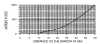
click on image to
enlarge
1-1-9. Instrument
Landing System (ILS)
a.
General
1.
The ILS is designed
to provide an approach path for exact alignment
and descent of an aircraft on final approach to a
runway.
2.
The ground equipment
consists of two highly directional transmitting
systems and, along the approach, three (or fewer)
marker beacons. The directional transmitters are
known as the localizer and glide slope
transmitters.
3.
The system may be
divided functionally into three parts:
(a) Guidance information:
localizer, glide slope;
(b) Range information:
marker beacon, DME; and
(c) Visual information:
approach lights, touchdown and centerline
lights, runway lights.
4.
Compass locators
located at the Outer Marker (OM) or Middle Marker
(MM) may be substituted for marker beacons. DME,
when specified in the procedure, may be
substituted for the OM.
5.
Where a complete ILS
system is installed on each end of a runway;
(i.e., the approach end of Runway 4 and the
approach end of Runway 22) the ILS systems are not
in service simultaneously.
b.
Localizer
1.
The localizer
transmitter operates on one of 40 ILS channels
within the frequency range of 108.10 to 111.95
MHz. Signals provide the pilot with course
guidance to the runway centerline.
2.
The approach course
of the localizer is called the front course and is
used with other functional parts, e.g., glide
slope, marker beacons, etc. The localizer signal
is transmitted at the far end of the runway. It is
adjusted for a course width of (full scale
fly-left to a full scale fly-right) of 700 feet at
the runway threshold.
3.
The course line along
the extended centerline of a runway, in the
opposite direction to the front course is called
the back course.
CAUTION-
Unless the aircraft's ILS equipment includes
reverse sensing capability, when flying inbound on
the back course it is necessary to steer the
aircraft in the direction opposite the needle
deflection when making corrections from off-course
to on-course. This "flying away from the needle"
is also required when flying outbound on the front
course of the localizer. Do not use back course
signals for approach unless a back course approach
procedure is published for that particular runway
and the approach is authorized by ATC.
4.
Identification is in
International Morse Code and consists of a
three-letter identifier preceded by the letter I (ll)
transmitted on the localizer frequency.
EXAMPLE-
I-DIA
5.
The localizer
provides course guidance throughout the descent
path to the runway threshold from a distance of 18
NM from the antenna between an altitude of 1,000
feet above the highest terrain along the course
line and 4,500 feet above the elevation of the
antenna site. Proper off-course indications are
provided throughout the following angular areas of
the operational service volume:
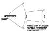
(a)
To 10 degrees
either side of the course along a radius of 18
NM from the antenna; and
(b)
From 10 to 35
degrees either side of the course along a radius
of 10 NM. (See FIG 1-1-6.)
FIG 1-1-6
Limits of Localizer Coverage
click on image to
enlarge
6.
Unreliable signals may be received outside these
areas.
c.
Localizer Type Directional Aid (LDA)
1.
The LDA is of
comparable use and accuracy to a localizer but is
not part of a complete ILS. The LDA course usually
provides a more precise approach course than the
similar Simplified Directional Facility (SDF)
installation, which may have a course width of 6
or 12 degrees.
2.
The LDA is not
aligned with the runway. Straight-in minimums may
be published where alignment does not exceed 30
degrees between the course and runway. Circling
minimums only are published where this alignment
exceeds 30 degrees.
d.
Glide Slope/Glide Path
1.
The UHF glide slope
transmitter, operating on one of the 40 ILS
channels within the frequency range 329.15 MHz, to
335.00 MHz radiates its signals in the direction
of the localizer front course. The term "glide
path" means that portion of the glide slope that
intersects the localizer.
CAUTION-
False glide slope signals may exist in the area of
the localizer back course approach which can cause
the glide slope flag alarm to disappear and
present unreliable glide slope information.
Disregard all glide slope signal indications when
making a localizer back course approach unless a
glide slope is specified on the approach and
landing chart.
2.
The glide slope
transmitter is located between 750 feet and 1,250
feet from the approach end of the runway (down the
runway) and offset 250 to 650 feet from the runway
centerline. It transmits a glide path beam 1.4
degrees wide (vertically). The signal provides
descent information for navigation down to the
lowest authorized decision height (DH) specified
in the approved ILS approach procedure. The
glidepath may not be suitable for navigation below
the lowest authorized DH and any reference to
glidepath indications below that height must be
supplemented by visual reference to the runway
environment. Glidepaths with no published DH are
usable to runway threshold.
3.
The glide path
projection angle is normally adjusted to 3 degrees
above horizontal so that it intersects the MM at
about 200 feet and the OM at about 1,400 feet
above the runway elevation. The glide slope is
normally usable to the distance of 10 NM. However,
at some locations, the glide slope has been
certified for an extended service volume which
exceeds 10 NM.
4.
Pilots must be alert
when approaching the glidepath interception. False
courses and reverse sensing will occur at angles
considerably greater than the published path.
5.
Make every effort to
remain on the indicated glide path.
CAUTION-
Avoid flying below the glide path to assure
obstacle/terrain clearance is maintained.
6.
The published glide
slope threshold crossing height (TCH) DOES NOT
represent the height of the actual glide path
on-course indication above the runway threshold.
It is used as a reference for planning purposes
which represents the height above the runway
threshold that an aircraft's glide slope antenna
should be, if that aircraft remains on a
trajectory formed by the four-mile-to-middle
marker glidepath segment.
7.
Pilots must be aware
of the vertical height between the aircraft's
glide slope antenna and the main gear in the
landing configuration and, at the DH, plan to
adjust the descent angle accordingly if the
published TCH indicates the wheel crossing height
over the runway threshold may not be satisfactory.
Tests indicate a comfortable wheel crossing height
is approximately 20 to 30 feet, depending on the
type of aircraft.
e.
Distance Measuring Equipment (DME)
1.
When installed with
the ILS and specified in the approach procedure,
DME may be used:
(a)
In lieu of the
OM;
(b)
As a back
course (BC) final approach fix (FAF); and
(c)
To establish
other fixes on the localizer course.
2.
In some cases, DME
from a separate facility may be used within
Terminal Instrument Procedures (TERPS)
limitations:
(a)
To provide ARC
initial approach segments;
(b)
As a FAF for BC
approaches; and
(c)
As a substitute
for the OM.
f.
Marker Beacon
1.
ILS marker beacons
have a rated power output of 3 watts or less and
an antenna array designed to produce an elliptical
pattern with dimensions, at 1,000 feet above the
antenna, of approximately 2,400 feet in width and
4,200 feet in length. Airborne marker beacon
receivers with a selective sensitivity feature
should always be operated in the "low" sensitivity
position for proper reception of ILS marker
beacons.
2.
Ordinarily, there are
two marker beacons associated with an ILS, the OM
and MM. Locations with a Category II ILS also have
an Inner Marker (IM). When an aircraft passes over
a marker, the pilot will receive the indications
shown in TBL 1-1-3.
(a)
The OM normally
indicates a position at which an aircraft at the
appropriate altitude on the localizer course
will intercept the ILS glide path.
(b)
The MM
indicates a position approximately 3,500 feet
from the landing threshold. This is also the
position where an aircraft on the glide path
will be at an altitude of approximately 200 feet
above the elevation of the touchdown zone.
(c)
The IM will
indicate a point at which an aircraft is at a
designated decision height (DH) on the glide
path between the MM and landing threshold.
TBL 1-1-3
Marker
Passage Indications
|
Marker
|
Code
|
Light
|
|
OM
|
-
-
- |
BLUE
|
|
MM
|
l
-
l
- |
AMBER
|
|
IM
|
l l l l
|
WHITE
|
|
BC
|
l l
l l |
WHITE
|
3.
A back course marker
normally indicates the ILS back course final
approach fix where approach descent is commenced.
g.
Compass Locator
1.
Compass locator
transmitters are often situated at the MM and OM
sites. The transmitters have a power of less than
25 watts, a range of at least 15 miles and operate
between 190 and 535 kHz. At some locations, higher
powered radio beacons, up to 400 watts, are used
as OM compass locators. These generally carry
Transcribed Weather Broadcast (TWEB) information.
2.
Compass locators
transmit two letter identification groups. The
outer locator transmits the first two letters of
the localizer identification group, and the middle
locator transmits the last two letters of the
localizer identification group.
h.
ILS Frequency
(See TBL
1-1-4.)
TBL 1-1-4
Frequency Pairs Allocated for ILS
|
Localizer MHz |
Glide Slope |
|
108.10
|
334.70
|
|
108.15
|
334.55
|
|
108.3
|
334.10
|
|
108.35
|
333.95
|
|
108.5
|
329.90
|
|
108.55
|
329.75
|
|
108.7
|
330.50
|
|
108.75
|
330.35
|
|
108.9
|
329.30
|
|
108.95
|
329.15
|
|
109.1
|
331.40
|
|
109.15
|
331.25
|
|
109.3
|
332.00
|
|
109.35
|
331.85
|
|
109.50
|
332.60
|
|
109.55
|
332.45
|
|
109.70
|
333.20
|
|
109.75
|
333.05
|
|
109.90
|
333.80
|
|
109.95
|
333.65
|
|
110.1
|
334.40
|
|
110.15
|
334.25
|
|
110.3
|
335.00
|
|
110.35
|
334.85
|
|
110.5
|
329.60
|
|
110.55
|
329.45
|
|
110.70
|
330.20
|
|
110.75
|
330.05
|
|
110.90
|
330.80
|
|
110.95
|
330.65
|
|
111.10
|
331.70
|
|
111.15
|
331.55
|
|
111.30
|
332.30
|
|
111.35
|
332.15
|
|
111.50
|
332.9
|
|
111.55
|
332.75
|
|
111.70
|
333.5
|
|
111.75
|
333.35
|
|
111.90
|
331.1
|
|
111.95
|
330.95
|
i. ILS Minimums
1.
The lowest authorized
ILS minimums, with all required ground and
airborne systems components operative, are:
(a) Category I.
Decision Height
(DH) 200 feet and Runway Visual Range (RVR)
2,400 feet (with touchdown zone and centerline
lighting, RVR 1,800 feet);
(b) Category II.
DH 100 feet and RVR
1,200 feet;
(c) Category IIIa.
No DH or DH below
100 feet and RVR not less than 700 feet;
(d) Category IIIb.
No DH or DH below
50 feet and RVR less than 700 feet but not less
than 150 feet; and
(e) Category IIIc.
No DH and no RVR
limitation.
NOTE-
Special authorization and equipment required for
Categories II and III.
j.
Inoperative ILS Components
1.
Inoperative localizer.
When the localizer
fails, an ILS approach is not authorized.
2.
Inoperative glide slope.
When the glide slope
fails, the ILS reverts to a nonprecision localizer
approach.
REFERENCE-
See the inoperative component table in the U.S.
Government Terminal Procedures Publication (TPP),
for adjustments to minimums due to inoperative
airborne or ground system equipment.
k.
ILS Course Distortion
1.
All pilots should be
aware that disturbances to ILS localizer and glide
slope courses may occur when surface vehicles or
aircraft are operated near the localizer or glide
slope antennas. Most ILS installations are subject
to signal interference by either surface vehicles,
aircraft or both. ILS CRITICAL AREAS are
established near each localizer and glide slope
antenna.
2.
ATC issues control
instructions to avoid interfering operations
within ILS critical areas at controlled airports
during the hours the Airport Traffic Control Tower
(ATCT) is in operation as follows:
(a) Weather Conditions.
Less than ceiling 800 feet and/or visibility 2
miles.
(1) Localizer
Critical Area.
Except for aircraft that land, exit a runway,
depart or miss approach, vehicles and aircraft
are not authorized in or over the critical
area when an arriving aircraft is between the
ILS final approach fix and the airport.
Additionally, when the ceiling is less than
200 feet and/or the visibility is RVR 2,000 or
less, vehicle and aircraft operations in or
over the area are not authorized when an
arriving aircraft is inside the ILS MM.
(2) Glide Slope
Critical Area.
Vehicles and aircraft are not authorized in
the area when an arriving aircraft is between
the ILS final approach fix and the airport
unless the aircraft has reported the airport
in sight and is circling or side stepping to
land on a runway other than the ILS runway.
(b) Weather Conditions.
At or above ceiling
800 feet and/or visibility 2 miles.
(1)
No critical
area protective action is provided under these
conditions.
(2)
A flight
crew, under these conditions, should advise
the tower that it will conduct an AUTOLAND or
COUPLED approach to ensure that the ILS
critical areas are protected when the aircraft
is inside the ILS MM.
EXAMPLE-
Glide slope signal not protected.
3.
Aircraft holding
below 5,000 feet between the outer marker and the
airport may cause localizer signal variations for
aircraft conducting the ILS approach. Accordingly,
such holding is not authorized when weather or
visibility conditions are less than ceiling 800
feet and/or visibility 2 miles.
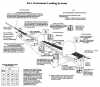
4.
Pilots are cautioned
that vehicular traffic not subject to ATC may
cause momentary deviation to ILS course or glide
slope signals. Also, critical areas are not
protected at uncontrolled airports or at airports
with an operating control tower when weather or
visibility conditions are above those requiring
protective measures. Aircraft conducting coupled
or autoland operations should be especially alert
in monitoring automatic flight control systems.
(See FIG 1-1-7.)
NOTE-
Unless otherwise coordinated through Flight
Standards, ILS signals to Category I runways are
not flight inspected below 100 feet AGL. Guidance
signal anomalies may be encountered below this
altitude.
FIG
1-1-7
FAA Instrument Landing Systems
click on image to
enlarge
1-1-10. Simplified Directional
Facility (SDF)
a.
The SDF provides a
final approach course similar to that of the ILS
localizer. It does not provide glide slope
information. A clear understanding of the ILS
localizer and the additional factors listed below
completely describe the operational characteristics
and use of the SDF.
b.
The SDF transmits
signals within the range of 108.10 to 111.95 MHz.
c.
The approach techniques
and procedures used in an SDF instrument approach
are essentially the same as those employed in
executing a standard localizer approach except the
SDF course may not be aligned with the runway and
the course may be wider, resulting in less
precision.
d.
Usable off-course
indications are limited to 35 degrees either side of
the course centreline. Instrument indications
received beyond 35 degrees should be disregarded.
e.
The SDF antenna may be
offset from the runway centreline. Because of this,
the angle of convergence between the final approach
course and the runway bearing should be determined
by reference to the instrument approach procedure
chart. This angle is generally not more than 3
degrees. However, it should be noted that inasmuch
as the approach course originates at the antenna
site, an approach which is continued beyond the
runway threshold will lead the aircraft to the SDF
offset position rather than along the runway
centreline.
f.
The SDF signal is fixed
at either 6 degrees or 12 degrees as necessary to
provide maximum flyability and optimum course
quality.
g.
Identification consists
of a three-letter identifier transmitted in Morse
Code on the SDF frequency. The appropriate
instrument approach chart will indicate the
identifier used at a particular airport.
|