|
1-1-11. Microwave Landing
System (MLS)
a. General
1.
The MLS provides precision
navigation guidance for exact alignment and
descent of aircraft on approach to a runway. It
provides azimuth, elevation, and distance.
2.
Both lateral and vertical guidance
may be displayed on conventional course deviation
indicators or incorporated into multipurpose
cockpit displays. Range information can be
displayed by conventional DME indicators and also
incorporated into multipurpose displays.
3.
The MLS supplements the ILS as the
standard landing system in the U.S. for civil,
military, and international civil aviation. At
international airports, ILS service is protected
to 2010.
4.
The system may be divided into five
functions:
(a)
Approach azimuth;
(b)
Back azimuth;
(c)
Approach elevation;
(d)
Range; and
(e)
Data communications.
5.
The standard configuration of MLS
ground equipment includes:
(a)
An azimuth station to perform
functions (a) and (e) above. In addition to
providing azimuth navigation guidance, the
station transmits basic data which consists of
information associated directly with the
operation of the landing system, as well as
advisory data on the performance of the ground
equipment.
(b)
An elevation station to
perform function (c).
(c)
Distance Measuring Equipment
(DME) to perform range guidance, both standard
DME (DME/N) and precision DME (DME/P).
6. MLS Expansion
Capabilities.
The
standard configuration can be expanded by adding
one or more of the following functions or
characteristics.
(a) Back
azimuth.
Provides
lateral guidance for missed approach and
departure navigation.
(b) Auxiliary
data transmissions.
Provides additional data, including refined
airborne positioning, meteorological
information, runway status, and other
supplementary information.
(c)
Expanded Service Volume (ESV)
proportional guidance to 60 degrees.
7.
MLS identification is a four-letter
designation starting with the letter M. It is
transmitted in International Morse Code at least
six times per minute by the approach azimuth (and
back azimuth) ground equipment.
b. Approach
Azimuth Guidance
1.
The azimuth station transmits MLS
angle and data on one of 200 channels within the
frequency range of 5031 to 5091 MHz.
2.
The equipment is normally located
about 1,000 feet beyond the stop end of the
runway, but there is considerable flexibility in
selecting sites. For example, for heliport
operations the azimuth transmitter can be
collocated with the elevation transmitter.
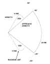
3.
The azimuth coverage extends:
(a)
Laterally, at least 40
degrees on either side of the runway centerline
in a standard configuration,
(b)
In elevation, up to an angle
of 15 degrees and to at least 20,000 feet, and
(c)
In range, to at least 20 NM.
FIG 1-1-8
Coverage Volume
Azimuth
click on image to enlarge
c. Elevation Guidance
1.
The elevation station transmits
signals on the same frequency as the azimuth
station. A single frequency is time-shared between
angle and data functions.
2.
The elevation transmitter is
normally located about 400 feet from the side of
the runway between runway threshold and the
touchdown zone.
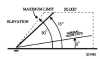
3.
Elevation coverage is provided in
the same airspace as the azimuth guidance signals:
(a)
In elevation, to at least +15
degrees;
(b)
Laterally, to fill the
Azimuth lateral coverage; and
(c)
In range, to at least 20 NM.
(See FIG 1-1-9.)
FIG 1-1-9
Coverage Volumes
Elevation
click on image to enlarge
d. Range Guidance
1.
The MLS Precision Distance
Measuring Equipment (DME/P) functions the same as
the navigation DME described in paragraph
1-1-7, Distance Measuring Equipment (DME), but
there are some technical differences. The beacon
transponder operates in the frequency band 962 to
1105 MHz and responds to an aircraft interrogator.
The MLS DME/P accuracy is improved to be
consistent with the accuracy provided by the MLS
azimuth and elevation stations.
2.
A DME/P channel is paired with the
azimuth and elevation channel. A complete listing
of the 200 paired channels of the DME/P with the
angle functions is contained in FAA Standard 022
(MLS Interoperability and Performance
Requirements).
3.
The DME/N or DME/P is an integral
part of the MLS and is installed at all MLS
facilities unless a waiver is obtained. This
occurs infrequently and only at outlying, low
density airports where marker beacons or compass
locators are already in place.
e. Data
Communications
1.
The data transmission can include
both the basic and auxiliary data words. All MLS
facilities transmit basic data. Where needed,
auxiliary data can be transmitted.
2. Coverage
limits. MLS data are
transmitted throughout the azimuth (and back
azimuth when provided) coverage sectors.
3. Basic data
content. Representative
data include:
(a)
Station identification;
(b)
Exact locations of azimuth,
elevation and DME/P stations (for MLS receiver
processing functions);
(c)
Ground equipment performance
level; and
(d)
DME/P channel and status.
4. Auxiliary
data content:
Representative data include:
(a)
3-D locations of MLS
equipment;
(b)
Waypoint coordinates;
(c)
Runway conditions; and
(d)
Weather (e.g., RVR, ceiling,
altimeter setting, wind, wake vortex, wind
shear).
f. Operational
Flexibility
1.
The MLS has the capability to
fulfill a variety of needs in the approach,
landing, missed approach and departure phases of
flight. For example:
(a)
Curved and segmented
approaches;
(b)
Selectable glide path angles;
(c)
Accurate 3-D positioning of
the aircraft in space; and
(d)
The establishment of
boundaries to ensure clearance from obstructions
in the terminal area.
2.
While many of these capabilities
are available to any MLS-equipped aircraft, the
more sophisticated capabilities (such as curved
and segmented approaches) are dependent upon the
particular capabilities of the airborne equipment.
g. Summary
1. Accuracy.
The MLS provides
precision three-dimensional navigation guidance
accurate enough for all approach and landing
maneuvers.
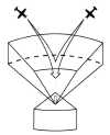
2. Coverage.
Accuracy is consistent
throughout the coverage volumes. (See FIG 1-1-10.)
FIG 1-1-10
Coverage Volumes
3-D Representation
click on image to enlarge
3. Environment.
The
system has low susceptibility to interference from
weather conditions and airport ground traffic.
4. Channels.
MLS has 200 channels-
enough for any foreseeable need.
5. Data.
The MLS transmits ground-air
data messages associated with the systems
operation.
6. Range
information.
Continuous
range information is provided with an accuracy of
about 100 feet.

1-1-12. NAVAID Identifier
Removal During Maintenance
During periods of
routine or emergency maintenance, coded identification
(or code and voice, where applicable) is removed from
certain FAA NAVAID's. Removal of identification serves
as a warning to pilots that the facility is officially
off the air for tune-up or repair and may be
unreliable even though intermittent or constant
signals are received.
NOTE-
During periods of maintenance VHF ranges may radiate a
T-E-S-T code (-llll-
).
1-1-13. NAVAID's with Voice
a.
Voice equipped en route radio
navigational aids are under the operational control
of either an FAA Automated Flight Service Station (AFSS)
or an approach control facility. The voice
communication is available on some facilities. The
Hazardous Inflight Weather Advisory Service (HIWAS)
broadcast capability on selected VOR sites is in the
process of being implemented throughout the
conterminous U.S. and does not provide voice
communication. The availability of two-way voice
communication and HIWAS is indicated in the A/FD and
aeronautical charts.
b.
Unless otherwise noted on the chart,
all radio navigation aids operate continuously
except during shutdowns for maintenance. Hours of
operation of facilities not operating continuously
are annotated on charts and in the A/FD.
1-1-14. User Reports on
NAVAID Performance
a.
Users of the National Airspace System
(NAS) can render valuable assistance in the early
correction of NAVAID malfunctions by reporting their
observations of undesirable NAVAID performance.
Although NAVAID's are monitored by electronic
detectors, adverse effects of electronic
interference, new obstructions or changes in terrain
near the NAVAID can exist without detection by the
ground monitors. Some of the characteristics of
malfunction or deteriorating performance which
should be reported are: erratic course or bearing
indications; intermittent, or full, flag alarm;
garbled, missing or obviously improper coded
identification; poor quality communications
reception; or, in the case of frequency
interference, an audible hum or tone accompanying
radio communications or NAVAID identification.
b.
Reporters should identify the NAVAID,
location of the aircraft, time of the observation,
type of aircraft and describe the condition
observed; the type of receivers in use is also
useful information. Reports can be made in any of
the following ways:
1.
Immediate report by direct radio
communication to the controlling Air Route Traffic
Control Center (ARTCC), Control Tower, or FSS.
This method provides the quickest result.
2.
By telephone to the nearest FAA
facility.
3.
By FAA Form 8000-7, Safety
Improvement Report, a postage-paid card designed
for this purpose. These cards may be obtained at
FAA FSS's, Flight Standards District Offices, and
General Aviation Fixed Base Operations.
c.
In aircraft that have more than one
receiver, there are many combinations of possible
interference between units. This can cause either
erroneous navigation indications or, complete or
partial blanking out of the communications. Pilots
should be familiar enough with the radio
installation of the particular airplanes they fly to
recognize this type of interference.
1-1-15. LORAN
a. Introduction
1.
LORAN, which uses a network of
land-based radio transmitters, was developed to
provide an accurate system for LOng RAnge
Navigation. The system was configured to provide
reliable, all weather navigation for marine users
along the U.S. coasts and in the Great Lakes. The
current system, known as LORAN-C, was the third
version of four developed since World War II.
2.
With an expanding user group in the
general aviation community, the LORAN coastal
facilities were augmented in 1991 to provide
signal coverage over the entire continental U.S.
The FAA and the U.S. Coast Guard (USCG) are
incorporating LORAN into the NAS for supplemental
en route and nonprecision approach operations.
LORAN-C is also supported in the Canadian airspace
system. This guide is intended to provide an
introduction to the LORAN system, LORAN avionics,
the use of LORAN for aircraft navigation, and to
examine the possible future of LORAN in aviation.
b. LORAN Chain
1.
The 27 U.S. LORAN transmitters that
provide signal coverage for the continental U.S.
and the southern half of Alaska are distributed
from Caribou, ME, to Attu Island in the Aleutians.
Station operations are organized into sub-groups
of four to six stations called "chains." One
station in the chain is designated the "Master"
and the others are "secondary" stations.
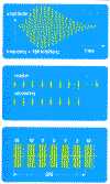
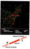
2.
The LORAN navigation signal is a
carefully structured sequence of brief radio
frequency pulses centered at 100 kHz. The sequence
of signal transmissions consists of a pulse group
from the Master (M) station followed at precise
time intervals by groups from the secondary
stations which are designated by the U.S. Coast
Guard with the letters V, W, X, Y and Z. All
secondary stations radiate pulses in groups of
eight, but the Master signal for identification
has an additional ninth pulse.
3.
The time interval between the
reoccurrence of the Master pulse group is the
Group Repetition Interval (GRI). The GRI is the
same for all stations in a chain and each LORAN
chain has a unique GRI. Since all stations in a
particular chain operate on the same radio
frequency, the GRI is the key by which a LORAN
receiver can identify and isolate signal groups
from a specific chain.
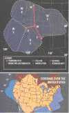
EXAMPLE-
Transmitters in the northeast U.S. chain operate
with a GRI of 99,600 microseconds which is
shortened to 9960 for convenience. The master
station (m) at Sseneca, NY, controls: secondary
stations (w) at Caribou, ME; (x) at Nantucket, MA;
(y) at Carolina Beach, NC; and (z) at Dana, IN. In
order to keep chain operations precise, the system
uses monitor receivers at Cape Elizabeth, ME,
Sandy Hook, NJ and Plumbrook, OH. Monitor
receivers continuously measure various aspects of
the quality and accuracy of LORAN signals and
report system status to a control station where
chain timing is maintained.
4.
The line between the Master and
each secondary station is the "baseline" for a
pair of stations. Typical baselines are from 600
to 1,000 nautical miles in length. The
continuation of the baseline in either direction
is a "baseline extension."
5.
LORAN transmitter stations have
time and control equipment, a transmitter,
auxiliary power equipment, a building about 100 by
30 feet in size and an antenna that is about 700
feet tall. A station generally requires
approximately 100 or more acres of land to
accommodate guy lines that keep the antenna in
position. Each LORAN station transmits from 400 to
1,600 kilowatts of signal power.
6.
The USCG operates 27 stations,
comprising eight chains, in the U.S. NAS. Four
control stations, which monitor chain performance,
have personnel on duty full time. The Canadian
east and west coast chains also provide signal
coverage over small areas of the NAS.
7.
When a control station detects a
signal problem that could affect navigation
accuracy, an alert signal called "Blink" is
activated. Blink is a distinctive change in the
group of eight pulses that can be recognized
automatically by a receiver so the user is
notified instantly that the LORAN system should
not be used for navigation. In addition, other
problems can cause signal transmissions from a
station to be halted.
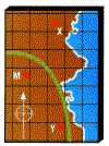
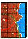
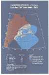
8.
Each individual LORAN chain
provides navigation-quality signal coverage over
an identified area as shown for the West Coast
chain, GRI 9940. The chain Master station is at
Fallon, NV, and secondary stations are at George,
WA; Middletown, CA; and Searchlight, NV. In a
signal coverage area the signal strength relative
to the normal ambient radio noise must be adequate
to assure successful reception.
FIG 1-1-11
LORAN C
Pulse
click on image to enlarge
FIG 1-1-12
LORAN C
Northeast U.S. Chain
click on image to enlarge
c. The LORAN Receiver
1.
Before a LORAN receiver can provide
navigation information for a pilot, it must
successfully receive, or "acquire," signals from
three or more stations in a chain. Acquisition
involves the time synchronization of the receiver
with the chain GRI, identification of the Master
station signals from among those checked,
identification of secondary station signals, and
the proper selection of the point in each signal
at which measurements should be made.
2.
Signal reception at any site will
require a pilot to provide location information
such as approximate latitude and longitude, or the
GRI to be used, to the receiver. Once activated,
most receivers will store present location
information for later use.
3.
The basic measurements made by
LORAN receivers are the differences in
time-of-arrival between the Master signal and the
signals from each of the secondary stations of a
chain. Each "time difference" (TD) value is
measured to a precision of about 0.1 microseconds.
As a rule of thumb, 0.1 microsecond is equal to
about 100 feet.
4.
An aircraft's LORAN receiver must
recognize three signal conditions:
(a)
Usable signals;
(b)
Absence of signals; and
(c)
Signal blink.
5.
The most critical phase of flight
is during the approach to landing at an airport.
During the approach phase the receiver must detect
a lost signal, or a signal Blink, within 10
seconds of the occurrence and warn the pilot of
the event.
6.
Most receivers have various
internal tests for estimating the probable
accuracy of the current TD values and consequent
navigation solutions. Tests may include
verification of the timing alignment of the
receiver clock with the LORAN pulse, or a
continuous measurement of the signal-to-noise
ratio (SNR). SNR is the relative strength of the
LORAN signals compared to the local ambient noise
level. If any of the tests fail, or if the
quantities measured are out of the limits set for
reliable navigation, then an alarm will be
activated to alert the pilot.
7.
LORAN signals operate in the low
frequency band around (100 kHz) that has been
reserved for LORAN use. Adjacent to the band,
however, are numerous low frequency communications
transmitters. Nearby signals can distort the LORAN
signals and must be eliminated by the receiver to
assure proper operation. To eliminate interfering
signals, LORAN receivers have selective internal
filters. These filters, commonly known as "notch
filters" reduce the effect of interfering signals.
8.
Careful installation of antennas,
good metal-to-metal electrical bonding, and
provisions for precipitation noise discharge on
the aircraft are essential for the successful
operation of LORAN receivers. A LORAN antenna
should be installed on an aircraft in accordance
with the manufacturer's instructions. Corroded
bonding straps should be replaced, and static
discharge devices installed at points indicated by
the aircraft manufacturer.
FIG 1-1-13
LORAN- C
West Coast Chain
click on image to enlarge
d. LORAN Navigation
1.
An airborne LORAN receiver has four
major parts:
(a)
Signal processor;
(b)
Navigation computer;
(c)
Control/display; and
(d)
Antenna.
2.
The signal processor acquires LORAN
signals and measures the difference between the
time-of-arrival of each secondary station pulse
group and the Master station pulse group. The
measured TD's depend on the location of the
receiver in relation to the three or more
transmitters.
FIG 1-1-14
First
Line-of-Position
click on image to enlarge
(a) The first TD will
locate an aircraft somewhere on a
line-of-position (LOP) on which the receiver
will measure the same TD value.
(b)
A second LOP is defined by a
TD measurement between the Master station signal
and the signal from another secondary station.
FIG 1-1-15
Second
Line-of-Position
click on image to enlarge
FIG 1-1-16
Intersection of
Lines-of-Position
click on image to enlarge
(c) The intersection
of the measured LOP's is the position of the
aircraft.
3.
The navigation computer converts TD
values to corresponding latitude and longitude.
Once the time and position of the aircraft is
established at two points, distance to
destination, cross track error, ground speed,
estimated time of arrival, etc., can be
determined. Cross track error can be displayed as
the vertical needle of a course deviation
indicator, or digitally, as decimal parts of a
mile left or right of course. During a
nonprecision approach, course guidance must be
displayed to the pilot with a full scale deviation
of ±0.30 nautical miles or greater.
4.
LORAN navigation for non-precision
approaches requires accurate and reliable
information. During an approach the occurrence of
signal Blink or loss of signal must be detected
within 10 seconds and the pilot must be notified.
LORAN signal accuracy for approaches is 0.25
nautical miles, well within the required accuracy
of 0.30 nautical miles. LORAN signal accuracy can
be improved by applying correction values.
5.
Flying a LORAN nonprecision
approach is different from flying a VOR approach.
A VOR approach is on a radial of the VOR station,
with guidance sensitivity increasing as the
aircraft nears the airport. The LORAN system
provides a linear grid, so there is constant
guidance sensitivity everywhere in the approach
procedure. Consequently, inaccuracies and
ambiguities that occur during operations in close
proximity to VOR's (station passage, for example)
do not occur in LORAN approaches.
6.
The navigation computer also
provides storage for data entered by pilot or
provided by the receiver manufacturer. The
receiver's database is updated at local
maintenance facilities every 60 days to include
all changes made by the FAA.
7.
The FAA is currently canceling all
LORAN nonprecision approaches with the advent of
Global Positioning System (GPS).
e.
Notices to Airmen (NOTAM's) are
issued for LORAN-C chain or station outages.
Domestic NOTAM (D)'s are issued under the identifier
"LRN." International NOTAM's are issued under the
KNMH series. Pilots may obtain these NOTAM's from
FSS briefers upon request.
FIG 1-1-17
North Pacific
Chain

click on image to enlarge
FIG 1-1-18
Coverage Over
Alaska

click on image to enlarge
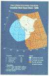
FIG 1-1-19
Canadian West
Coast Chain
click on image to enlarge
FIG 1-1-20
U.S. West Coast
Chain

click on image to enlarge
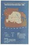
FIG 1-1-21
North Central
U.S. Chain
click on image to enlarge
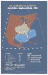
FIG 1-1-22
South Central
U.S. Chain

click on image to enlarge
FIG 1-1-23
U.S. Great Lakes
Chain

click on image to enlarge
FIG 1-1-24
U.S. Southeast
Chain
click on image to enlarge
FIG 1-1-25
Northeast U.S.
Chain

click on image to enlarge
FIG 1-1-26
Canadian East
Coast Chain
click on image to enlarge
f. LORAN-C status
information
Prerecorded telephone
answering service messages pertaining to LORAN-C are
available in
TBL 1-1-5 and
TBL 1-1-6.
g.
The U.S. will continue to operate the
LORAN-C system in the short term beyond the
previously planned December 31, 2000, termination
date while continuing to evaluate the long-term need
for continuation of the system. Users will be given
reasonable notice if it is concluded that LORAN-C is
not needed or is not cost effective, so that they
will have the opportunity to transition to
alternative navigation aids.
TBL 1-1-5
Prerecorded LORAN-C
Status Information
Rate
|
Chain
|
Telephone
|
|
5930
|
Canadian East
Coast |
(709) 454-3261*
|
|
7980
|
Southeast U.S.
|
(904) 569-5241
|
|
8970
|
Great Lakes
|
(607) 869-5395
|
|
9960
|
Northeast U.S.
|
(607) 869-5395
|
|
*St. Anthony,
Newfoundland, Canada.
Information can also be obtained directly from
the office of the Coordinator of Chain
Operations (COCO) for each chain. The following
telephone numbers are for each COCO office.
|
TBL 1-1-6
LORAN-C Coordinator of Chain Operations
Telephone Numbers
Rate
|
Chain
|
Telephone
|
Location
|
|
4990
|
Central
Pacific |
808-247-5591
|
Kaneohe, HI
|
|
5930
|
Canadian East
Coast |
709-454-2392
|
St. Antony,
NF |
|
5990
|
Canadian West
Coast |
604-666-0472
|
Vancover, BC
|
|
7930
|
North
Atlantic |
011-44-1-409-4758 |
London, UK
|
|
7960
|
Gulf of
Alaska |
907-487-5583
|
Kodiak, AK
|
|
7970
|
Norwegian Sea
|
011-44-1-409-4758 |
London, UK
|
|
7980
|
Southeast
U.S. |
205-899-5225
|
Malone, FL
|
|
7990
|
Mediterranean
Sea |
011-44-1-409-4758 |
London, UK
|
|
8290
|
North Central
U.S. |
707-987-2911
|
Middletown,
CA |
|
8970
|
Great Lakes
|
607-869-5393
|
Seneca, NY
|
|
9610
|
South Central
U.S. |
205-899-5225
|
Malone, FL
|
|
9940
|
West Coast
U.S. |
707-987-2911
|
Middletown,
CA |
|
9960
|
Northeast
U.S. |
607-869-5393
|
Seneca, NY
|
|
9970
|
Northwest
Pacific |
415-437-3224
|
San
Francisco, CA |
|
9990
|
North Pacific
|
907-487-5583
|
Kodiak, AK |
1-1-16. OMEGA and OMEGA/Very Low
Frequency (VLF) Navigation Systems
OMEGA operations were
terminated on September 30, 1997.
1-1-17. VHF Direction Finder
a.
The VHF Direction Finder (VHF/DF) is
one of the common systems that helps pilots without
their being aware of its operation. It is a
ground-based radio receiver used by the operator of
the ground station. FAA facilities that provide
VHF/DF service are identified in the A/FD.
b.
The equipment consists of a
directional antenna system and a VHF radio receiver.
c.
The VHF/DF receiver display indicates
the magnetic direction of the aircraft from the
ground station each time the aircraft transmits.
d.
DF equipment is of particular value
in locating lost aircraft and in helping to identify
aircraft on radar.
REFERENCE-
AIM, Direction Finding Instrument Approach
Procedure, Paragraph
6-2-3.
d. Special
Category I Differential GPS (SCAT-I DGPS)
1.
The SCAT-I DGPS is designed to
provide approach guidance by broadcasting
differential correction to GPS.
2.
SCAT-I DGPS procedures require
aircraft equipment and pilot training.
3.
Ground equipment consists of GPS
receivers and a VHF digital radio transmitter. The
SCAT-I DGPS detects the position of GPS satellites
relative to GPS receiver equipment and broadcasts
differential corrections over the VHF digital
radio.
4.
Category I Ground Based
Augmentation System (GBAS) will displace SCAT-I
DGPS as the public use service.
REFERENCE-
AIM, Instrument Approach Procedures, Paragraph
5-4-7f.
|