|
|
|

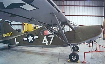
Stinson L 5 Sentinel performance and specifications
|
In 1939,
Stinson entered the light-plane market with the
Model 105. An improved Model 10 Voyager was
introduced in 1941.
Six Model 10s were tested by the U.S. Army under
the designation YO-54 and purchased with a more
powerful engine as the O-62.
The O-62 designation was changed to the "L" for
Liaison L-5 designation in 1942. 3,590 were
ordered making the L-5 the second most widely used
AAF liaison aircraft.
Almost 500 L-5s were transferred to the U.S. Navy
and Marine Corps and received the designation
OY-1.
The unarmed L-5 was used for reconnaissance,
removing litter patients from front areas,
delivering supplies to isolated units, laying
communication wire, spotting targets, transporting
personnel, rescuing personnel in remote areas and
even as a light bomber.
In 1962 surviving L-5s were re-designated U-19 by
the U.S. Air Force.
|
Average Empty Weight
.............................................L-5
.........................1480 lbs.
.............................................L-5B
.......................1520 lbs.
.............................................L-5C........................1540
lbs
.............................................L-5E:
.......................1560 lbs
.............................................L-5G
.......................1600 lbs
Standard Gross Weight
............................................L-5..........................
2050 lbs.
............................................L-5B
thru L-5E........ 2150 lbs.
............................................L-5G
.......................2250 lbs.
Crew
Capacity: 400 lbs
Cargo Capacity: 250 lbs (no passenger)
Wing Loading: 13.8 lb / sq. ft. |
|
The powerplant is a horizontally opposed
Lycoming 6-cylinder design. It is
direct-drive, air-cooled, and normally
aspirated. The cylinders have steel barrels
with aluminium heads, and the valves are
operated by hydraulic lifters. The crankshaft
is supported in an aluminium-alloy split case
by four main bearings and one ball-thrust
bearing, and lubricating oil is supplied from
a 12 quart wet sump. The camshaft rides in
journals that do not employ bearing inserts.
The accessory housing supports two magnetos, a
starter, a generator, and a dual tach drive. A
spare mounting pad is included for a vacuum
pump.
Engine (L-5 thru
L-5E)......................... Lycoming
O-435-1
........................(L-5G)........................
Lycoming O-435-11Displacement.......................................
435 cubic inches
Compression
Ratio.............................. 6.5 : 1
Maximum Rated Power (takeoff)......... 185 hp
at 2550 rpm (O-435-1)
...........................................................190hp
at 2550 rpm (O-435-11)
Normal Operating Range.....................
1900 - 2300 rpm
Induction............................................
Marvel-Schebler MA-4-5 carburettor
Fuel...................................................
73 or 80/85 octane.
Engine
Weight.................................... 350
to 379 lbs.
Power Loading:
.................................14.33 lb / hp |
|
Fahlin or Sensenich 85" diameter fixed-pitch
wood
or
Koppers Aeromatic 220 85" diameter
variable-pitch metal
or
Hartzell HC12x20-4..85" diameter
variable-pitch metal |
|
Fuselage construction is fabric over welded
4130 steel tubing and aluminium stringers. The
doors are fabric covered plywood, and the boot
cowl and engine cowlings are aluminium. The
cantilevered main gear legs and tailwheel unit
are welded steel and damped with oleo shock
absorbers. The telescoping tailwheel oleo also
employs a coil spring to prevent rapid
bottoming of the strut.
Length: 24' 1.25"
Height: 7' 1"
Track: 7' 1"
Wheelbase: 18' 6"
Seating: Two in tandem |
|
The wings are fabric covered and feature solid
laminated wooden spars and built-up plywood
ribs. All but the two outer ribs are
identical. The leading and trailing edges are
formed plywood, and the ply-sheeted bottoms
act as shear panels, negating the need for
internal bracing. The flaps and ailerons are a
framework of aluminium covered with fabric,
and the fixed leading edge slats are also
aluminium. The flaps are a 3-position slotted
type and manually operated by steel cables.
The ailerons are actuated by a combination of
cables in the fuselage and aluminium torque
tubes in the wings.
Wing Span: 33'
11.62
Wing chord: 4' 9"
Wing dihedral: 2
1/2 degrees
Wing area: 155
sq. ft.
Airfoil: NACA
4412 (flat bottom)
Aileron span: 7'
6" each (total area 18.02 sq. ft.)
Flap span: 6' 8"
each ( total area 12.22 sq. ft.)
Wing Slots: 3' 2"
span each. |
|
Basic Performance
and Limitations |
Maximum Level
Speed................................. 128 mph
at 2550 rpm
Maximum Dive
Speed................................... 208
mph at 3050 rpm
Normal Climb
Speed.................................... 85
mph at 2300 rpm
Normal Cruise
Speed................................... 110
mph at 2250 rpm
Maximum Speed Flaps Extended..................
100 mph
Stall Speed:
(power-off, flaps up)...................57 mph
...................(power-on, flaps
down)..............43 mph
Maximum Power
Limitation.......................... 2550 rpm
for 5 minutes
Service
Ceiling..............................................15,600
ft. |
|
