
drag
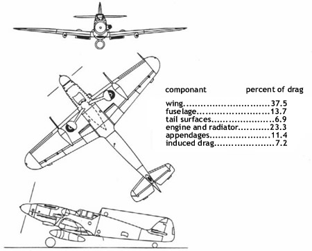
This figure shows a Me-109G German fighter from
World War II. Shown is the percentage breakdown of
the drag (includes interference drag) of the
components
Any physical body being propelled through the air
has drag associated with it. In aerodynamics, drag
is defined as the force that opposes forward motion
through the atmosphere and is parallel to the
direction of the free-stream velocity of the
airflow. Drag must be overcome by thrust in order to
achieve forward motion.
Drag is generated by nine conditions associated with
the motion of air particles over the aircraft. There
are several types of drag: form, pressure, skin
friction, parasite, induced, and wave.
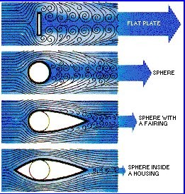
The term "separation" refers to the smooth flow of
air as it closely hugs the surface of the wing then
suddenly breaking free of the surface and creating a
chaotic flow. The second picture on the left hand
margin of this page shows examples of air flowing
past a variety of objects. The bottom shows well
behaved, laminar flow (flow in layers) where the
flow stays attached (close to the surface) of the
object. The object just above has a laminar flow for
the first half of the object and then the flow
begins to separate from the surface and form many
chaotic tiny vortex flows called vortices. The two
objects just above them have a large region of
separated flow. The greater the region of separated
flow, the greater the drag. This is why airplane
designers go to such effort to streamline wings and
tails and fuselages — to minimize drag.
Induced drag
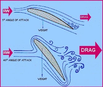
Induced drag is a by-product of lift
Induced drag is the drag created by the
vortices at the tip of an aircraft's wing.
Induced drag is the drag due to lift. The
high pressure underneath the wing causes the airflow
at the tips of the wings to curl around from bottom
to top in a circular motion. This results in a
trailing vortex. Induced drag increases in direct
proportion to increases in the angle of attack. The
circular motion creates a change in the angle of
attack near the wing tip which causes an increase in
drag. The greater the angle of attack up to the
critical angle (where a stall takes place), the
greater the amount of lift developed and the greater
the induced drag.
All of these types of drag must be accounted for
when determining drag for subsonic flight. The
total drag is the sum of parasite and induced
drag.
Total Drag = Parasite Drag + Induced Drag
But the net (or total) drag of an aircraft is not
simply the sum of the drag of its components. When
the components are combined into a complete
aircraft, one component can affect the air flowing
around and over the airplane, and hence, the drag of
one component can affect the drag associated with
another component. These effects are called
interference effects, and the change in the sum
of the component drags is called interference
drag. Thus,
(Drag)1+2 = (Drag)1 + (Drag)2
+ (Drag)interference
Generally, interference drag will add to the
component drags but in a few cases, for example,
adding tip tanks to a wing, total drag will be less
than the sum of the two component drags because of
the reduction of induced drag.
parasite drag
The parasite drag of a typical
airplane in the cruise configuration consists
primarily of the skin friction, roughness, and
pressure drag of the major components. There is
usually some additional parasite drag due to such
things as fuselage upsweep, control surface gaps,
base areas, and other extraneous items. Since most
of the elements that make up the total parasite drag
are dependent on Reynolds number and since some are
dependent on Mach number, it is necessary to specify
the conditions under which the parasite drag is to
be evaluated. In the method of these notes, the
conditions selected are the Mach number and the
Reynolds number corresponding to the flight
condition of interest.
The basic parasite drag area for
airfoil and body shapes can be computed from the
following expression:
f = k cf Swet
where the skin friction
coefficient, cf , which is based on the
exposed wetted area includes the effects of
roughness, and the form factor, k, accounts for the
effects of both supervelocities and pressure drag. Swet
is the total wetted area of the body or surface.
Computation of the overall
parasite drag requires that we compute the drag area
of each of the major components (fuselage, wing,
nacelles and pylons, and tail surfaces) and then
evaluate the additional parasite drag components
described above.
We thus write:
CDp =
S
ki cfi Sweti
/ Sref + CDupsweep + CDgap+
CDnac_base + CDmisc
where the first term includes skin friction, and
pressure drag at zero lift of the major components.
cfi is the average skin
friction coefficient for a rough plate with
transition at flight Reynolds number. Equivalent
roughness is determined from flight test data.
form drag
Form
drag and pressure drag are virtually the same
type of drag. Form or pressure drag is caused by the
air that is flowing over the aircraft or airfoil.
The separation of air creates turbulence and results
in pockets of low and high pressure that leave a
wake behind the airplane or airfoil (thus the name
pressure drag). This opposes forward motion and is a
component of the total drag. Since this drag is due
to the shape, or form of the aircraft, it is also
called form drag. Streamlining the aircraft will
reduce form drag, and parts of an aircraft that do
not lend themselves to streamlining are enclosed in
covers called fairings, or a cowling for an engine,
that have a streamlined shape. Airplane components
that produce form drag include (1) the wing and wing
flaps, (2) the fuselage, (3) tail surfaces, (4)
nacelles, (5) landing gear, (6) wing tanks and
external stores, and (7) engines.
Skin
friction drag is caused by the actual contact
of the air particles against the surface of the
aircraft. This is the same as the friction between
any two objects or substances. Because skin friction
drag is an interaction between a solid (the airplane
surface) and a gas (the air), the magnitude of skin
friction drag depends on the properties of both the
solid and the gas. For the solid airplane, skin
fiction drag can be reduced, and airspeed can be
increased somewhat, by keeping an aircraft's surface
highly polished and clean. For the gas, the
magnitude of the drag depends on the viscosity of
the air. Along the solid surface of the airplane, a
boundary layer of low energy flow is generated. The
magnitude of the skin friction depends on the state
of this flow.
skin
friction
The leading edge of a wing will
always produce a certain amount of friction drag
An important aerodynamic force
during low-speed subsonic flight is the shear force
(the sideways force or internal friction) caused by
viscous airflow over the surfaces of the vehicle.
This shear force is referred to as the skin-friction
force or skin-friction drag and depends strongly on
the Reynolds number, surface roughness, and pressure
gradients. In addition to the pressure forces that
act everywhere perpendicular to (normal to) a body
in moving air, viscous forces are also present. It
is these viscous forces that modify the lift that
would exist under ideal conditions (air is inviscid
and incompressible) and help create the real drag.
If the airflow were ideal, that is, inviscid, the
air would simply slip over the surface of a smooth
plate with velocity V¥. At all points along the
surface of the plate, the velocity distribution
(that is, the variation in velocity as one moves
perpendicularly away from the surface) would be a
uniform constant value of V∞. No drag would result
if the airflow were frictionless (inviscid).
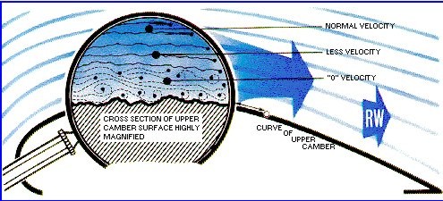
Under real conditions, however, a very thin film of
air molecules adheres to the surface. This is the
very important no-slip condition. It states that at
the surface of a body, the airflow velocity is zero.
As one moves away from the body, the velocity of the
air gradually increases until, at some point, the
velocity becomes a constant value; in the case of a
flat plate this value is V¥. The layer of air where
the velocity is changing from zero to a constant
value is called the boundary layer. Within the
boundary layer, there are relative velocities
between the layers and an internal friction is
present. This internal friction extends to the
surface of the body. The cumulative effect of all
these friction forces is to produce drag on the
plate. This drag is referred to as skin-friction
drag.
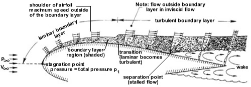
Real fluid flow about an airfoil. The thickness of
the boundary layers and wake are greatly
exaggerated. The bottom flow along lower surface is
the same as on the upper surface.
Initially, near the leading edge
of a flat, smooth plate, one has a laminar flow (the
flow is layered) and the boundary layer also is
steady and layered—hence, a laminar boundary layer.
As one moves farther downstream, viscosity continues
to act, and the laminar boundary layer thickens as
more and more air is slowed down by internal
friction. Eventually, a point is reached on the
plate where the laminar boundary layer undergoes
transition and becomes a turbulent boundary layer.
As is usual for turbulent flow, there is random
motion in the boundary layer as well as the
downstream-directed motion. There is no slip at the
surface of the plate. Another important difference
from the laminar boundary layer is the fact that the
velocity builds up more quickly as one moves away
from the wall, although the total boundary-layer
thickness is greater. The turbulent boundary layer
farther away from the wall reenergizes the slower
moving air nearer the wall. This condition can be
seen by comparing the profile of the laminar
boundary layer with the profile of the turbulent
boundary layer.
The Reynolds number has an important effect on the
boundary layer. As the Reynolds number increases
(caused by increasing the airflow speed and/or
decreasing the viscosity), the boundary layer
thickens more slowly. However, even though the
Reynolds number becomes large, the velocity at the
surface of the body must be zero. Thus, the boundary
layer never disappears.
It is interesting to note that a typical thickness
of the boundary layer on an aircraft wing is
generally less than a centimetre (2.5 inches). Yet,
the velocity must vary from zero at the surface of
the wing to hundreds of meters per second at the
outer edge of the boundary layer. It is evident that
tremendous shearing forces (internal friction) must
be acting in this region. This gives rise to the
skin-friction drag.
Applied to an airfoil in a real airflow, the same
free-stream velocity V¥ and free-stream static
pressure p¥ apply. The field of air ahead of the
airfoil is only slightly modified and for all
practical purposes, the velocities and static
pressures are the same as for the ideal fluid case.
Again a stagnation point (a point with no motion)
occurs at the leading edge of the airfoil and the
pressure reaches its maximum value of pt at this
point (total or stagnation pressure). From this
point on along the airfoil, the picture changes.
As noted earlier in the example of the flat plate, a
boundary layer begins to form because of viscosity.
This boundary layer is very thin and outside of it,
the flow acts very much like that of an ideal fluid.
Also, the static pressure acting on the surface of
the airfoil is determined by the static pressure
outside the boundary layer. This pressure is
transmitted through the boundary layer to the
surface and thus acts as if the boundary layer were
not present at all. But the boundary layer feels
this static pressure and will respond to it.
Over the front surface of the airfoil up to the
shoulder, an assisting favourable pressure gradient
exists (pressure decreasing with distance
downstream). The airflow speeds up along the
airfoil. The flow is laminar and a laminar boundary
layer is present. This laminar boundary layer grows
in thickness along the airfoil. When the shoulder is
reached, however, the air molecules are moving
slower than in the ideal fluid case. This is an
unfavourable condition because the previous ideal
flow just came to rest at the trailing edge of the
airfoil. It would appear now, with viscosity
present, that the flow will come to rest at some
distance before the trailing edge is reached.
As the airflow moves from the shoulder to the rear
surface of the airfoil, the static-pressure gradient
is unfavourable (increasing pressure with downstream
distance). The air molecules must push against both
this unfavourable pressure gradient and the viscous
forces. At the transition point, the character of
the airflow changes and the laminar boundary layer
quickly becomes a turbulent boundary layer. This
turbulent boundary layer continues to thicken
downstream. Pushing against an unfavourable pressure
gradient and viscosity is too much for the airflow,
and at some point, the airflow stops completely. The
boundary layer has stalled short of reaching the
trailing edge. (Remember that the airflow reached
the trailing edge before stopping in the ideal fluid
case.)
This stall point is known as the separation point.
All along a line starting from this point outward
into the airflow, the airflow is stalling. Beyond
this line, the airflow is actually moving backward,
upstream toward the nose before turning around. This
is a region of eddies and whirlpools and represents
“dead” air that is disrupting the flow field away
from the airfoil. Thus, the airflow outside the dead
air region is forced to flow away and around it. The
region of eddies is called the wake behind the
airfoil.
Up to the separation point, the difference between
the static-pressure distribution for ideal fluid
flow and real airflow is not very large but once
separation occurs, the pressure field in greatly
modified. In the ideal fluid case, the net
static-pressure force acting on the front surface of
the airfoil (up to the shoulder) parallel to the
free stream exactly opposed and cancelled that
acting on the rear surfaces of the airfoil. Under
real airflow conditions, however, this symmetry and
cancellation of forces is destroyed. The net
static-pressure force acting on the front surface
parallel to the free-stream direction now exceeds
that acting on the rear surface. The net result is a
drag force due to the asymmetric pressure
distribution called pressure drag. This is a drag in
addition to the skin-friction drag due to the
shearing forces (internal friction) in the boundary
layer. Additionally, the modification of the
static-pressure distribution causes a decrease in
the pressure lift from the ideal fluid case. The
effect of viscosity is that the lift is reduced and
a total drag composed of skin-friction drag and
pressure drag is present. Both of these are
detrimental effects.
It should be emphasized that similar processes are
occurring on all the components of the aircraft to
one degree or another, not only the airfoil.
Thus, the effects of a real fluid flow are the
result of the viscosity of the fluid. The viscosity
causes a boundary layer and, hence, a skin-friction
drag. The flow field is disrupted because of
viscosity to the extent that a pressure drag arises.
Also, the net pressure lift is reduced.
interference
drag
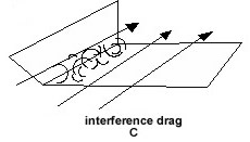
Surfaces at angles to each other
as in (C) create turbulence in the region of the
joint. This occurs most frequently at the
intersection of the fuselage and wing.
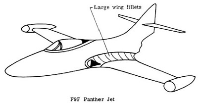
This figure shows a Grumman F9F
Panther Jet with a large degree of filleting to
reduce drag
lift
versus drag
An aircraft
with a given total gross weight can be operated in
level flight over a range of power settings and
airspeeds. Since Lift and Weight must be equal in
order to maintain level flight, it is obvious that
there is a relationship between Lift (L), Airspeed
(V), and Angle of Attack (AT). This relationship can
be "generalized" with the following expression.
(Note: the expression is not an exact equation).
Lift = Angle
of Attack x Velocity
Since angle of
attack and speed also have a relationship to Induced
Drag and Parasite Drag, the relationship of
Lift/Drag is shown by the graph below.
Parasite
drag increases with speed. Induced drag decreases
with speed. The SUM of the two drags (Total Drag
curve) shows that there is only one airspeed for a
given airplane and load that provides MINIMUM total
drag. This is the point M which is the maximum lift
over drag ratio (L/D). It is the airspeed at which
the aircraft can glide the farthest without power
(maximum glide range). This is the airspeed which
should immediately be set up in the event of a power
failure. This maximum glide airspeed is different
for each aircraft design. The Pilot Operating
Handbook should be consulted for this airspeed and
the pilot should memorize it to eliminate need to
search manuals during an emergency.
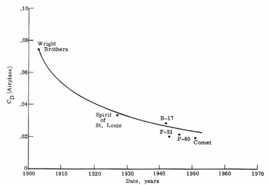
Decrease in airplane drag coefficient
with time
|
