|
|

methods of reducing
induced drag
Induced drag is caused by the generation of lift. It is created by the
vortices at the tip of an aircraft's wing. The magnitude of induced drag
depends on the amount of lift being generated by the wing and on the shape
and size of the wing. Long, thin (chord wise) wings have low induced drag;
short wings with a large chord have high induced drag.
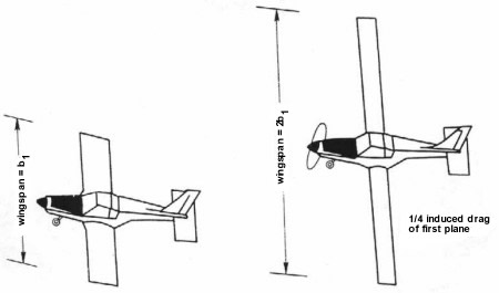
This
figure illustrates the wing-span effect on induced drag for airplanes
having same wing area, same lift coefficient, and same dynamic pressure.
How can
the induced drag be reduced? One may (1) increase the span efficiency
factor to as close to e = 1 as possible, (2) increase the wing span b (or
aspect ratio AR), and (3) increase the free-stream velocity V¥. Induced
drag is a small component at high speeds (cruising flight) and relatively
unimportant since it constitutes only about 5 to 15 percent of the total
drag at those speeds. But at low speeds (takeoff or landing), it is a
considerable component since it accounts for up to 70 percent of the total
drag.
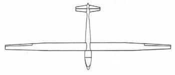
High
aspect-ratio wing
The
efficiency factor e and wing span are physical factors that may be
controlled by proper design. A plane with a longer span wing (higher
aspect ratio) has less induced drag and, therefore, greater efficiency.
But structural considerations become a dominant factor. A very thin long
wing requires a large structural weight to support it, and there comes a
point where the disadvantage of increasing structural weight needed to
support the increased wing span counteracts the advantage of decreased
drag due to smaller vortex effects. An aircraft with a compromise aspect
ratio, and which also considers factors such as fuel capacity, control
characteristics, size allowances, and numerous other factors, would give
the optimum performance. A survey of airplane categories shows sailplanes
with an aspect ratio of 15 or more, single-engine light airplanes with an
aspect ratio of about 6, and supersonic fighter airplanes with an aspect
ratio of about 2.
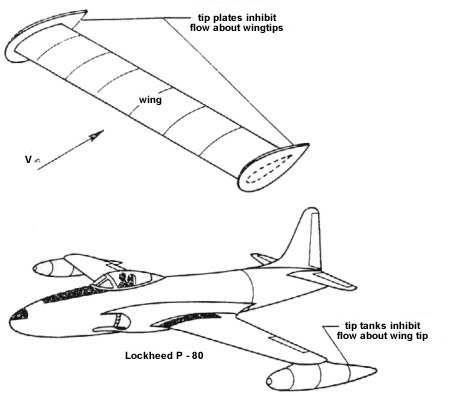
Tip
plates and tip tanks
An
interesting way of reducing induced drag is by the use of tip plates or
tip tanks. This arrangement tends to inhibit the formation of tip
vortices. Tip plates have the same physical effect as an increase in wing
span (or aspect ratio). Normally, these are not used since there are other
more valuable drag reduction methods.
For a general wing, the airfoil sections may vary in three distinct ways
along the wing. First, the size or chord length may change; second, the
shape of the airfoil section may change as one moves along the wing, and
lastly, the angles of attack of the airfoil sections may change along the
wing.
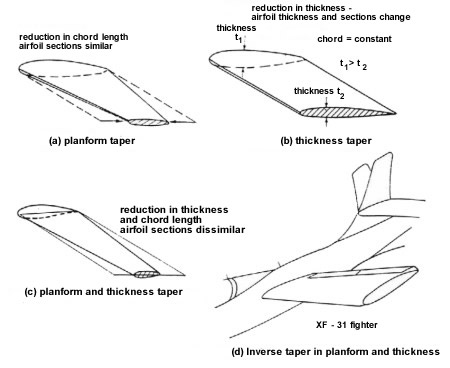
Planform and thickness taper
Planform taper is the reduction of the chord length and thickness as one
proceeds from the root (near the fuselage) to the tip section (at the wing
tip) so that the airfoil sections also remain geometrically similar. (A
planform is the shape of the wing as one looks down on it from above.)
Thickness taper is the reduction of the airfoil's thickness as one
proceeds from the root section (the part of the wing closest to the
fuselage) to the tip section. This reduction results in thinner airfoil
sections at the wing tip. The chord remains constant. One notable
exception to this normal taper was the XF-91 fighter, which has inverse
taper in planform and thickness so that the wing tips were thicker and
wider than the inboard stations.
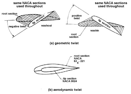
Geometric and aerodynamic twist
Wings are given twist so that the angle of attack varies along the span. A
decrease in angle of attack toward the wing tip is called washout whereas
an increase in angle of attack toward the wing tip is called wash-in.
Geometric twist represents a geometric method of changing the lift
distribution, whereas aerodynamic twist changes lift by using different
airfoil sections along the span—an aerodynamic method of changing the lift
distribution in a span wise manner. To give minimum induced drag, the span
wise efficiency factor e should be as close to 1 as possible. This is the
case of an elliptic span wise lift distribution. A number of methods are
available to modify the span wise distribution of lift. They include (1)
planform taper to obtain an elliptic planform, used for the Spitfire wing,
which was remarkably elliptic; (2) a geometric twist and/or aerodynamic
twist to obtain elliptic lift distribution; or (3) a combination of all of
these methods.
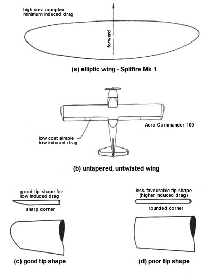
Reduction of induced drag. A square-tipped rectangular wing is almost as
efficient as the elliptic wing
An elliptical planform is hard to manufacture and is costly. From the
point of view of construction, the best type of wing is the un-tapered,
untwisted wing. This is often used by light plane manufacturers.
Surprisingly, data indicates that a square-tipped rectangular wing is very
nearly as efficient as the elliptic wing, so that the gains in reduced
induced drag may be insignificant. This result may be traced to the fact
that, for a real wing, the lift distribution falls off to zero at the wing
tips and approximates an elliptical distribution.
The wing-tip shape, being at the point where the tip vortices are
produced, appears to be of more importance in minimizing tip vortex
formation and thus minimizing induced drag. Taper and twist are perhaps of
greater importance in dealing with the problem of stalling.
|
|
