
manoeuvring forces
our thanks
www.raa.asn.au
(Copyright John Brandon)
The performance of an
aircraft in the hands of a competent pilot – at a
given altitude – results from the sum of power and
attitude. Power provides thrust and consequently
forward acceleration, lift, drag and radius of
turn. Attitude is the angle of the longitudinal
axis with the horizon (often called the 'pitch'
which also has another meaning associated with
propellers) plus the angle of attack and the
angle of bank. Attitude dictates the direction and
dimension of the lift, thrust and drag vectors and
consequently converts power into velocities and
accelerations in the three planes. There is a
third factor – energy management – which is an art
that supplements attitude plus power to produce
maximum aircraft performance. The epitome of such
an art is demonstrated by air-show pilots who
produce extraordinary performances from otherwise
relatively mundane aeroplanes.
Cruise performance
When
an aircraft is in cruise mode, i.e. flying from
point A to point B, the pilot has several options
for cruise speed. One choice might be to get there
as soon as possible, in which case she/he would
operate the engine at the maximum continuous power
allowed by the engine designer. The recommended
maximum continuous power is usually around 75% of
the rated power of the engine and provides
performance cruise. Another choice might be to
get there using as little fuel as possible, but in a
reasonable time, in which case the pilot might
choose a 55% power setting to provide the economy
cruise airspeed. Or the pilot might choose any
power setting, in the usual engine design range,
between 55% and 75%.
(Rated
power is the brake horsepower delivered at the
propeller shaft of a direct drive engine, operating
at maximum design rpm and best power fuel/air
mixture, in standard sea level air density
conditions. An engine is only operated at its rated
capacity for short periods during flight. Rated
power for small aero-engines is usually expressed as
brake horsepower rather than the SI unit of
kilowatts.
The power required
curve
In
level flight at constant speed the power is only
required to balance drag. Power is the rate of doing
work so power (watts) is force (newtons) × distance
(metres) / time (seconds). Distance/time is velocity
so power required is drag force (N) × velocity (v)
Thus if we use the expression for total drag in
section 1.6 and multiply it by v we get:-
Power
required for level flight =
CD
× ½rV³ × S
watts [note V³ ]
The total drag curve in the section 1.6 diagram can be converted into a
'power required' curve – usually called the power
curve – if you know the total drag at each
airspeed between the minimum controllable speed and
the maximum level flight speed. It will be a
different curve to that for total drag, because the
power required is proportional to velocity cubed
rather than velocity squared: which means that if
speed is doubled drag is increased four-fold but
power must be increased eight times. Which indicates
why increasing power output from say 75% to full
rated power (100%) while holding level flight
doesn't provide a corresponding increase in airspeed
– see below.
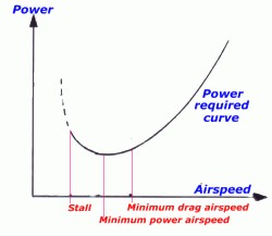
The
diagram above is a typical level flight power curve
for a light aeroplane, the part of the curve to the
left of the minimum power airspeed is known as the
back of the power curve where the slower you
want to fly the more power is needed, because of the
induced drag at the high angles of attack of low
speeds. The lowest possible speed for controlled
flight is the stall speed, which we will
discuss in the 'Airspeed and air properties' module.
Two cruise speeds are indicated – the speed
associated with minimum power and the speed
associated with minimum drag. The former is known as
Vbe and the latter as Vbr.
Power available
The engine provides power to the propeller. The
propellers used in most light aircraft have a
maximum efficiency factor, in the conversion of
engine power to thrust power, of no more than 80%.
(Thrust power = thrust × forward
velocity). The pitch of the blades, the speed of
rotation of the propeller and the forward velocity
of the aircraft all establish the angle of attack of
the blades and the thrust delivered. The in-flight
pitch of light aircraft propeller blades is usually
fixed so that the maximum efficiency will occur at
one combination of rpm and forward velocity; this is
usually in the mid-range between best rate of climb
and the performance cruise airspeeds. Propeller
blades are sometimes pitched to give the maximum 80%
efficiency near the best rate of climb speed, or
pitched for best efficiency at the performance
cruise airspeed. The former is a climb prop
and the latter a cruise prop. The efficiency
of all types falls off either side of the maximum;
one with too high pitch angle may have a very poor
take-off performance; one with too low pitch may
allow the engine to overspeed at any time.
Speed, power
and altitude
At
sea level an aero engine will deliver its rated
power – provided it is in near perfect ex-factory
condition, properly warmed up and using fuel in
appropriate condition. However as air density
decreases with altitude, and an engine's performance
is dependent on the weight of the charge delivered
to the cylinders, then the full throttle power of a
non-supercharged four-stroke engine will decrease
with height, so that at about 6000 – 7000 feet the
maximum power available at full throttle may drop
below 75% of rated power. At 12 000 feet full
throttle power may be less than 55% rated power.
Thus as altitude increases the range of cruise power
airspeeds decreases. For best engine performance
select a cruise altitude where the throttle is fully
open and the engine is delivering 65% – 75% power.
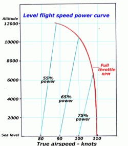
A
couple of points to note in the speed-power diagram
above: firstly as air density, and consequently
drag, reduces with height then airspeed from a
particular power level will increase with height;
e.g. the airspeed attained with 65% power at sea
level is 90 knots increasing to 100 knots at 10 000
feet. Secondly at sea level an increase in power
from 75% to 100% only results in an increase in
airspeed from 100 to 110 knots. This is the norm
with most light aircraft – that last 33% power
increase to rated power only provides a 10% increase
in airspeed.
Power required vs power available
In
the diagram below, power available curves have been
added to the power required curve. The upper curve
indicates the rated power i.e. the full throttle
engine power delivered to the propeller over the
range of level flight speeds at sea level. The
second curve, maximum available thrust power, is
that engine power converted by the propeller after
allowing for 80% maximum propeller efficiency. The
third curve is the propeller thrust power available
with the engine throttled back to 75% power at sea
level, or, if flying at an altitude such that full
throttle opening will only deliver 75% of rated
power. The intersection of those power available
curves with the power required curve indicates the
maximum cruise speed in each condition.
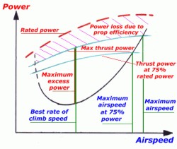
The
region between the green maximum available thrust
power curve and the power required curve indicates
the excess power available at various cruise speeds,
and this excess power is available for various
manoeuvres. The simplest use would be a straight
unaccelerated climb, in which case the maximum rate
of climb would be achieved at the airspeed where the
two curves are furthest apart; this airspeed is Vy;
best rate of climb speed. It can be seen that the Vy
is about the same airspeed as the speed for minimum
drag – Vbr – shown in the powered required curve.
It is important to remember that the rate of climb
will decrease at any speed either side of Vy because
the power available for climb decreases. The rate of
climb (metres/second) = excess power available
(watts)/aircraft weight (newtons).
Forces in a climb
It
was said above that in cruise the difference between
the current power requirement and power available –
the excess power – can be used to accelerate
the aircraft or climb, to accelerate and climb, or
perform any manoeuvre which requires additional
power. For instance if the pilot has potential power
available and opens the throttle the thrust will
exceed drag and the pilot can utilise that extra
thrust to accelerate to a higher speed while
maintaining level flight. Alternatively the pilot
can opt to maintain the existing speed but use the
extra thrust to climb to a higher altitude. The
rate of climb (altitude gained per minute)
depends on the amount of available power utilised
for climbing, which depends in part on the airspeed
chosen for the climb. There are other choices than
Vy available for the climb speed, for example
Vx the best angle of climb speed or a
combination enroute cruise/climb speed.
If an aircraft is maintained in a continuous
full-throttle climb at the best rate of climb
airspeed the rate of climb will be highest at sea
level and decrease with altitude as engine power
decreases. It will eventually arrive at an altitude
where the excess power available for climb reaches
zero. All the available power is required to balance
the drag in level flight, and there will be only one
airspeed at which level flight can be maintained
and, below which, the aircraft will stall. This
altitude is the aircraft's absolute ceiling.
However unless trying for an altitude record there
is no point in attempting to climb to the absolute
ceiling so the aircraft's service ceiling
should appear in the aircraft's performance
specification. The service ceiling is the altitude
at which the rate of climb falls below 100 feet per
minute, such being considered the minimum useful
rate of climb.
This diagram of forces in the climb and the
subsequent expressions, have been simplified,
aligning the angle of climb with the line of thrust.
In fact the line of thrust will usually be 4° to 10°
greater than the climb angle. The climb angle
is the angle the flight path subtends with the
horizon.
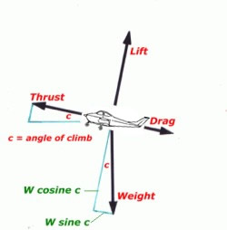
The
relationships in the triangle of forces shown is:-
Lift = weight × cosine c
Thrust = drag + (weight × sine c)
In a constant climb the forces are again in
equilibrium but now thrust plus lift = drag plus
weight.
Probably the most surprising thing about the
triangle of forces in a straight climb is that lift
is less than weight! For example let's put the
Jabiru into a 10° climb with weight = 4000 newtons.
(There is an
abridged
trig. table at the end of this page.)
then Lift = W cos c = 4000 × 0.985 = 3940
newtons
It is power that provides a continuous rate of
climb, but momentum may also be used as a temporary
energy exchange expedient, refer section 1.11 below.
It is evident from the above that in a steady climb
the rate of climb (and descent) is controlled with
power and the airspeed and angle of climb is
controlled with the attitude. This is somewhat of a
simplification as the pilot employs both power and
attitude in unison to achieve a particular angle and
rate of climb or descent.
A very important consideration,
particularly when manoeuvring at low level at normal
speeds, is that the steeper the climb angle the more
thrust is required to counter weight. For example if
you pulled the Jabiru up into a 30° climb the thrust
required = drag + weight × sine 30° and sine 30° =
0.5 so the engine has to provide sufficient thrust
to pull up half the weight plus overcome the
increased drag due to the increased aoa in the
climb. Clearly not possible so the airspeed will
fall off very rapidly and will lead to a dangerous
situation if the pilot is slow in getting the nose
down to an achievable attitude.
Forces in a descent
If
an aircraft is cruising at, for instance, the
maximum 75% power speed and the pilot reduces the
throttle to 65% power, the drag now exceeds thrust
and the pilot has two options – maintain height
allowing the excess drag to slow the aircraft to the
level flight speed appropriate to 65% power or
maintain the existing speed and allow the aircraft
to enter a steady descent or sink. The rate of
descent (altitude lost per minute) depends on
the difference between the 75% power required for
level flight at that airspeed and the 65% power
utilised. This sink rate will remain constant as
long as the thrust plus weight, which are
together acting in a forward direction, are
exactly balanced by the lift plus drag, which are
together acting in a rearward direction. At a
constant airspeed the sink rate, and the angle of
descent, will vary if thrust is varied.
If the pilot now pushed forward on the control
column to a steeper angle of descent, while
maintaining the same throttle opening, the thrust
plus weight resultant vector becomes greater, the
aircraft accelerates with consequent increase in
thrust power and the acceleration continues until
the forces are again in equilibrium. Actually it is
difficult to hold a stable aircraft in such a fixed
angle "power dive" as the aircraft will be wanting
to climb – but an unstable aircraft might be wanting
to 'tuck under' i.e. increase the angle of dive,
even past the vertical.
When the pilot closes the throttle completely, there
is no thrust, the aircraft enters a gliding descent
and the forces are then as shown in the diagram on
the left. In the case of a constant rate descent the
weight is exactly balanced by the resultant force of
lift and drag. From the dashed parallelogram of
forces shown it can be seen that the tangent of the
angle of glide equals drag/lift.
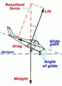
For
example assuming a glide angle of 10°, from the
table below the tangent of 10° is 0.176, so the
ratio of drag/lift in this case is then 1 : 5.7
Conversely we can say that the angle of glide is
dependent on the ratio of lift/drag and the higher
that ratio is then the smaller the glide angle and
consequently the further the aircraft will glide
from a given height.
e.g. calculating the optimum glide angle for an
aircraft with a L/D of 12 :1:-
Drag/lift equals 1/12 thus tangent = 0.08 and, from
the table below, the glide angle = 5°.
Although there is no thrust associated with the
power-off glide the power required curve in section
1.7 above is still relevant. The minimum drag
airspeed shown in that diagram is more or less the
airspeed for best glide angle – Vbg – and the speed
for minimum power is more or less the airspeed for
minimum rate of descent in a glide – Vmd.
Turning forces
In
aviation usage "g" denotes the force due to gravity.
When an aircraft is airborne at a constant velocity
and altitude the load on the aircraft wings is the
aircraft's mass and that load is expressed as being
equivalent to '1g'. Similarly when the aircraft is
parked on the ground the load on the aircraft wheels
[its weight] is a 1g load.
Any time an aircraft's velocity is changed there are
positive or negative accelerative forces applied to
the aircraft and its occupants. The resultant "load
factor" is normally measured in terms of "g"
load which is the ratio of the forces
experienced during the acceleration to the forces
existing at 1g.
You will come across expressions such as "2g turn"
or "pulled 2g"; what is being implied is that during
a particular manoeuvre a radial acceleration
was applied to the airframe and the load on the
wings doubles – for the Jabiru a 2g load = 400 kg ×
20 m/s² = 8000 newtons. The occupants will also feel
they weigh twice as much. This is 'radial g', or
centripetal force and it applies whether the
aircraft is changing direction in the horizontal
plane, the vertical plane or anything between.
You may also come across mention of "negative g". It
is conventional to describe g as positive when the
loading on the wing is in the normal direction. When
the load direction is reversed it is described as
negative. Slight negative g can occur momentarily in
severe turbulence but an aircraft experiencing a
sustained 1g negative loading is flying in
equilibrium, but upside down. It is also possible
for some high powered aerobatic aircraft to fly an
'outside' loop, i.e. the pilot's head is on the
outside of the loop rather than the inside, and the
aircraft (and it's very uncomfortable occupants),
will be experiencing various negative g values all
the way around the manoeuvre.
The structures of the aircraft we are concerned with
are required to withstand in-flight load factors not
less than +4.4g to –1.8g at MTOW without any
malformation – temporary or otherwise. In addition,
to allow for less than optimum craftmanship, a
'design safety factor' of at least 1.5 is added thus
the aircraft should normally cope with load factors
of +6.6g to – 2.7g.
It should not be thought that aircraft structures
are significantly weaker in the negative g
direction. The normal load is +1g so with a +4.4g
limit then an additional positive 3.4g load can be
applied while with a –1.8g limit an additional
negative load of 2.8g can be applied.
Centripetal force
When
an aircraft turns, in any plane, an additional force
must be continuously applied to overcome inertia,
particularly its normal tendency to continue in a
straight line. This is achieved by applying a force
towards the centre of the curve or arc – the
centripetal force – which is the product of the
aircraft mass and the acceleration required.
Remember that acceleration is the rate of
change of velocity, either speed or direction or
both. The acceleration, as you know from driving a
car through an S curve, depends on the speed at
which the vehicle is moving around the arc and the
radius of the turn. Slow speed and a sweeping turn –
very little acceleration, but high speed and holding
a small radius involves high acceleration with
consequent high radial g or centripetal force and
difficulty in holding the turn.
The acceleration towards the centre of the turn is
V²/r metres per second per second and the
centripetal force required to produce the turn is
m × V²/r Newtons where r is the turn radius in
metres and m is the aircraft mass in kilograms. Note
that we are using aircraft mass not weight.
Turn forces and bank
angle
The
diagram below shows the relationships between
centripetal force, weight, lift and bank angle.
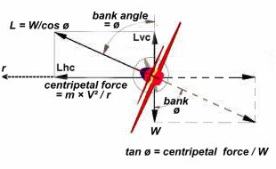
In a
level turn the vertical component of the lift
[Lvc] balances aircraft weight and the
horizontal component of lift [Lhc]
provides the centripetal force.
[Note: in a right angle triangle the tangent of
an angle is the ratio of the side opposite the angle
to that adjacent to the angle. Thus the tangent of
the bank angle is equal to the centripetal force
divided by the aircraft weight or tan ø = cf / W.
(Or it can be expressed as tan ø = V² /gr ).
In the diagram I have created a parallelogram of
forces so that all horizontal lines represent the
centripetal force or Lhc and all vertical
lines represent the weight or Lvc.]
|
Let's look at the Jabiru, mass 400 kg, in a
250 metre radius horizontal turn at a constant
speed of 97 knots or 50 m/s:-
Centripetal acceleration = V² / r = 50 × 50 /
250 = 10 m/s²
Centripetal force required = m × V² / r = m
×10 = 400 × 10 = 4000 newtons |
The centripetal force of 4000 N is provided by the
horizontal component of the lift force from the
wings when banked at an angle from the horizontal,
the correct bank angle being dependent on the
velocity and radius: think about a motorbike
taking a curve in the road. During the level
turn the lift force must also have a vertical
component to balance the aircraft's weight, in this
case also 4000 newtons. But the total required force
is not 4000 + 4000 N, rather we have to find the one
– and only one – bank angle where Lvc is
equal to the weight and Lhc is equal to
the required centripetal force.
What then will be the correct bank angle [ø]
for a balanced turn? Well we can calculate it easily
if you have access to trigonometrical tables, if you
haven't there is a very
abridged
version at the end of this page.
|
So in a level turn requiring 4000 N
centripetal force with weight 4000 N the tangent
of the bank angle = 4000/4000 = 1.0 and thus the
angle = 45°. Actually the bank angle would be
45° for any aircraft of any weight moving at 97
knots in a turn radius of 250 metres – provided
the aircraft can fly at that speed of course.
(Do the sums with an aircraft of mass 2500 kg,
thus weight = 25 000 N.).
Now what total lift force will the wings need
to provide in our level turn if the weight
component is 4000 N and the radial component
also 4000 N?
Resultant total lift force = weight divided by
the cosine of the bank angle or L = W / cos ø.
Weight is 4000 N, cosine 45° is 0.707 =
4000/0.707 = 5660 N.
So the load on the structure – the wing
loading – in the turn, is 5660/4000 = 1.41
times normal or 1.41g. |
Wing loading
We know that lift =
CL
× ½rV² × S = Weight
thus W = CL
× ½rV² × S
or W / S =
CL
× ½rV² = the wing loading
From this we can see that if wing loading increases
in a constant speed manoeuvre then
CL
, the angle of attack, must increase. Conversely if
CL
, the angle of attack, is increased during a
constant speed manoeuvre the lift, and consequently
the wing loading, must increase.
It can be a little misleading when using terms
such as 2g. For instance we said earlier that a
lightly loaded Jabiru has a mass of 340 kg and if
you do the preceding centripetal force calculation
using that mass you will find that the centripetal
acceleration is 10 m/s², centripetal force is 3400
N, weight is 3400 N and total lift = 4800 N, i.e.
the actual wing loading is 20% less but it is still
a 1.41g turn, i.e. 4800/3400 = 1.41.
Thus rather than thinking in terms of g equivalents,
it may be more appropriate to consider the actual
loads being applied to the aircraft structures, and
the norm is to use the wing loading as the primary
structural load reference. In the prior case the
load on the wing structure is 5660 / 8 = 707 N/m²,
compared to the 500 newtons load per m² in normal
cruise.
Most general aviation aircraft have a designed
wing loading between 500 and 1000 N/m², ultralights
between 200 and 550 N/m², in normal cruise near
maximum allowed weight. Aircraft designed with
higher wing loading are usually more manoeuvrable,
are less affected by atmospheric turbulence, but
have higher minimum speed than aircraft with lower
wing loading. Wing loading is usually stated in
pounds per square foot; between 11 and 22 for GA
aircraft, 4 and 12 for ultralights.
Increasing the lift
force in a turn
You
might ask how does the Jabiru increase the lift if
it maintains the same cruise speed in the level
turn? Well the only value in the equation - Lift =
CL
× ½rV² × S - that can then be changed is the lift
coefficient, which must be increased by the pilot
increasing the angle of attack. Note that increasing
aoa will also increase induced drag, so that the
pilot must also increase thrust to maintain the same
airspeed; thus the maximum rate of turn for an
aircraft will also be limited by the amount of
additional power available to overcome induced drag.
Thus for a level turn the slowest possible speed and
the steepest possible bank angle will provide both
the smallest radius and the fastest rate of turn,
but there are limitations.
If you consider an aerobatic aircraft weighing 10
000 N and making a turn in the vertical plane, i.e.
the loop described earlier, and imagine that the
centripetal acceleration is 2g; what will be the
wing loading at various points of the turn?
Actually the centripetal acceleration varies all the
way around because the airspeed and radius must vary
but we will ignore that and say that it is 2g all
round. If the acceleration is 2g then the
centripetal force must be 20 000 N all the way
round.
A turn in the vertical plane differs from a
horizontal turn in that, at both sides of the loop,
the wings do not have to provide any lift component
to counter weight, just lift for the centripetal
force, so the total load at those points is 20 000 N
or 2g. At the top, with the aircraft inverted, the
weight is directed towards the centre of the turn
and provides 10 000 N of the centripetal force and
the wings need provide only 10 000 N. Thus the total
load is only 10 000 N or 1g, whereas at the bottom
of a continuing turn the wings provide all the
centripetal force plus counter the weight, so the
load there is 30 000 N or 3g.
This highlights an important point: when
acceleration loads are reinforced by the
acceleration of gravity, the total load can be very
high.
If you have
difficulty in conceiving the centripetal force
loading on the wings, think about it in terms of the
reaction momentum, centrifugal force which,
from within the aircraft, is seen as a force pushing
the vehicle and its occupants to the outside of the
turn and the lift (centripetal force) is
counteracting it. Centrifugal force is always
expressed as g multiples.
Conserving aircraft
energy
Energy available
An
aircraft in straight and level flight has:
-
linear momentum – m × v kg m/s
-
kinetic energy [the energy of a body due to its
motion] – ½mv² newton metres (or joules;
one joule = 1Nm)
-
gravitational potential energy – in this case the
product of weight in newtons and height gained in
metres
-
chemical potential energy in the form of fuel in
the tanks
-
and air resistance that dissipates some kinetic
energy as heat or atmospheric turbulence.
To simplify the text from here on we will refer to
'gravitational potential energy' as just potential
energy and "chemical potential energy" as just
chemical energy.
|
We can calculate the energy available to the
Jabiru cruising:
• at a height of 6500 feet [2000 metres]
• and velocity [air distance flown over time]=
97 knots [50 metres per second]
• with mass = 400 kg thus weight = 4000 newtons
• fuel = 50 litres.
Then:
• potential energy = weight × height = 4000 ×
2000 = 8 million joules
• kinetic energy = ½mv² = ½ × 400 × 50 × 50 =
500 000 joules
• momentum = mass × velocity = 400 × 50 = 20 000
units (kg m/s)
• chemical energy = 50 litres @ 7.5 million
joules = 375 million joules. |
Because it is the accumulation of the work done to
raise the aircraft 6500 feet, the potential energy
is 16 times the kinetic energy, and is obviously an
asset that you don't want to dissipate. It is
equivalent to 2% of your fuel.
One of the skills of piloting an aircraft is in the
art of managing energy for conservation and making
appropriate use of momentum. Fighter pilots take the
art of energy management to its limits – for
survival, but so should you – the only safe place to
have dissipated your potential and kinetic energy is
after the aircraft touches down on the runway. The
intelligent use of energy and momentum, for instance
exchanging potential for kinetic, or vice versa, is
a skill to be developed.
It is always wise to balance a shortage of potential
energy with an excess of kinetic energy, and vice
versa. For example if you don't have much height
then have some extra speed up your sleeve for
manoeuvring or to provide extra time for action in
case of engine or wind shear problems. Or if kinetic
energy is reduced by flying at lower speeds than
normal make sure you have ample height or, if
approaching to land, hold height for as long as
possible. The only time to be "low and slow" is when
you are about to land.
However during take-off it is not possible to
have an excess of either potential or kinetic energy
thus take-off is the most critical phase of flight,
closely followed by the go-around following an
aborted landing approach. Ensure that a safe climb
speed is achieved as quickly as possible after
becoming airborne – or commencing a go-around – and
before the climb-out is actually commenced.
Kinetic energy
measurement
Kinetic energy is a scalar quantity equal to ½mv²
joules if the aircraft is not turning. However the
velocity must be measured in relation to some frame
of reference and when we discuss inflight energy
management the aircraft velocity chosen is that
which is relative to the air, i.e. the true
airspeed. For a landborne [or about to landborne]
aircraft we are generally concerned with either the
work to be done to get the aircraft airborne or the
[impact] energy involved in bringing the aircraft to
a halt, so the velocity used is that which is
relative to the ground. Groundspeed represents the
horizontal component, rate of climb/descent the
vertical component of that velocity.
Kinetic energy, gravitational potential energy and
energy conservation are complex subjects. If you
wish to go further plug "kinetic energy" "reference
frame" into the Google search engine.
Momentum conversion
Let's look at momentum conversion. Take the Jabiru,
weighing 4000 newtons and cruising at 97 knots – 50
m/s – and the pilot decides to reduce the cruise
speed to 88 knots – 45 m/s. This could be
accomplished by reducing thrust, below that needed
for 88 knots, allowing drag to dissipate the excess
kinetic energy then increasing power for 88 knots.
However, if traffic conditions allow, the excess
kinetic energy can be converted to potential energy
by reducing power, but only to that needed to
maintain a 88 knot cruise, and at the same time,
pulling up – thus reducing airspeed but still
utilising momentum – then pushing over into level
flight just as the 88 knot airspeed is acquired.
|
How much height would be gained?
Consider this:
• kinetic energy at 97 knots = ½mv² = ½ × 400
× 50 × 50 = 500 000 joules
• kinetic energy at 88 knots = ½mv² = ½ × 400
× 45 × 45 = 405 000 joules
• kinetic energy available = 95 000 joules
(or newton metres)
• but potential energy = weight × height
joules (or newton metres)
• thus height (gained) = energy available
divided by weight
• = 95 000 Nm / 4000 N = 24 metres = 78 feet
or 9 feet gained per knot of speed converted. |
If
you recalculate the preceding figures doubling the
initial (100 m/s) and final velocities (90 m/s) the
height gained will increase fourfold to 96 metres,
or about 18 feet per knot. Conversely if we halve
the initial velocity to about 50 knots the height
gained per knot converted is halved, to about 4
feet. Note that as mass appears in both the kinetic
energy and the weight expressions, it can be
ignored, thus the figures are the same for any mass.
|
Abridged trigonometrical table
Relationship between an angle within a
right angle triangle and the sides:
Tangent of angle=opposite side/adjacent
Sine of angle=opposite/hypotenuse
Cosine of angle=adjacent/hypotenuse
|
|
Degrees |
Sine |
Cosine |
Tangent |
|
Degrees |
Sine |
Cosine |
Tangent |
|
1 |
0.017 |
0.999 |
0.017 |
|
50 |
0.766 |
0.643 |
1.192 |
|
5 |
0.087 |
0.996 |
0.087 |
|
55 |
0.819 |
0.574 |
1.428 |
|
10 |
0.173 |
0.985 |
0.176 |
|
60 |
0.866 |
0.500 |
1.732 |
|
15 |
0.259 |
0.966 |
0.268 |
|
65 |
0.910 |
0.423 |
2.145 |
|
20 |
0.342 |
0.939 |
0.364 |
|
70 |
0.939 |
0.342 |
2.747 |
|
30 |
0.500 |
0.866 |
0.577 |
|
75 |
0.966 |
0.259 |
3.732 |
|
40 |
0.643 |
0.766 |
0.839 |
|
80 |
0.985 |
0.173 |
5.672 |
|
45 |
0.707 |
0.707 |
1.000 |
|
90 |
1.000 |
0 |
infinity |
|
|
