
principles of
aerodynamics
attitude
The attitude
of an aircraft refers to it's relationship to the
ground. When in a level attitude, the longitudinal
centreline of the aircraft is approximately parallel
to the earth's surface. In this attitude, the
horizon will appear to be just about on the nose of
the aircraft( i.e. the top of the engine cowling is
approximately aligned with the horizon).
When the nose
of the aircraft is above the horizon, this is called
a nose high attitude. If the nose is below the
horizon, the aircraft is in a nose low attitude.
centre of gravity
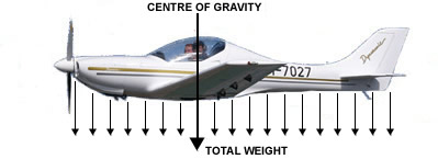
The weight of
the airplane, pilot and passengers, fuel and baggage
is distributed throughout the aircraft, as shown by
the small downward arrows in the diagram. However,
the total weight can be considered as being
concentrated at one given point, shown by the larger
downward arrow. This point is referred to as the
Centre of Gravity. If the plane were suspended by a
rope attached at the centre of gravity ( referred to
as the CG) it would be in balance.
The centre of
gravity (CG) is affected by the way an aircraft is
loaded. For example, if in a 4 place aircraft, there
are 2 rather large individuals in the front seats,
and no rear seat passengers or baggage, the CG will
be somewhat toward the nose of the aircraft. If
however, the 2 front seat passengers are smaller,
with 2 large individuals in the rear seats, and a
lot of baggage in the rear baggage compartment, the
CG will be located more aft.
Every aircraft
has a maximum forward and rearward CG position at
which the aircraft is designed to operate. Operating
an aircraft with the CG outside these limits affects
the handling characteristics of the aircraft.
Serious "out of CG" conditions can be dangerous.
aircraft balance
There is a balance point in the
middle (called a fulcrum), with weight on both sides
of the fulcrum. For an aircraft in straight and
level flight, the downward forces on both sides of the
fulcrum are equal.
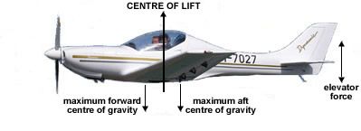
In the diagram
above, the fulcrum of an aircraft in flight is the
centre of lift. Generally the CG is forward of the
Centre of Lift, causing the aircraft to naturally
want to "nose down". The elevator located at the aft
end of the aircraft provides the counter-balancing
force to provide a level attitude in normal flight.
Normally, the pilot will "trim" the elevators, by
use of the trim tab control in the cockpit, to cause
the elevators to provide the correct elevator
balance force to relieve the pilot from constant
elevator control.
You can
readily see that loading of the aircraft, which
affects the CG, is a critical consideration in
properly balancing the aircraft and it's
controllability.
If the pilot
pulls back on the control wheel, an "up-elevator"
condition results. This forces the tail downward,
causing the aircraft to assume a "nose up" attitude.
Likewise, a forward movement of the control wheel by
the pilot causes a "down elevator" state. This
causes the tail to rise, forcing the aircraft into a
"nose low" attitude. By use of the elevator trim
control (a small wheel or crank in the cockpit), the
pilot can cause the aircraft to remain in a nose-up,
level, or nose down attitude.
As can be seen
in the diagram above, when the CG is forward, a
greater downward force is required by the elevators
to produce a level attitude. Likewise, when the CG
is aft, the elevators must produce less downward
force to maintain level flight. NOTE: If the CG gets
behind the Centre of lift (the fulcrum) the aircraft
becomes unstable because the CG is aft of the
fulcrum. IT MAY BE POSSIBLE TO EXCEED THE TRIM
CAPABILITY OF THE ELEVATORS SUCH THAT THE AIRCRAFT
ALWAYS WANTS TO NOSE UP, AND BE UNSTABLE. Therefore
the pilot must pay attention to proper loading of
the aircraft. This will be discussed in greater
detain under the subject of Weight and Balance.
effects of attitude change
When the
wing is in a given attitude with respect to the
Relative Wind (R W) as shown in the diagram below,
the wing produces a Vertical Lift Force (LIFT) which
is perpendicular to the Relative Wind..
There is also
a DRAG component operating parallel to the Relative
Wind in opposition to the forward motion of the
wing. Drag is created as a natural part of producing
lift. These two forces intersect at a point called
the CL (centre of lift}, or is also called the CP
(centre of pressure]. The LIFT and DRAG force
vectors can be resolved into a single force vector
called the RESULTANT force.
Envision if
the Angle of Attack is increased. The Vertical Lift
decreases in value, and the horizontal force of Drag
increases. Therefore, when a pilot wants to slow the
aircraft, the nose of the aircraft must be slowly
raised into a greater "nose up" attitude, causing
drag to increase, thus slowing the aircraft. This
increase of angle of attack has limits, however. The
wing design of most small aircraft, the wing has a
"Critical Angle Of Attack" (somewhere around 18° to
20°) at which point the wing ceases to create
sufficient lift to fly, and the wing STALLS. The air
flowing over the wing becomes so disturbed that
adequate lift to sustain flight ceases, and the
aircraft pitches "nose down". This is a STALL.
The primary
way to recover from a stall is to push the nose
further downward, thus decreasing the Angle Of
Attack so that the wing flies again.
Also, envision
in the diagram, when the pilot pushes the nose down
by use of forward elevator, the Angle of Attack
decreases, thus decreasing the drag. Therefore, when
power is held constant, the angle of attack (nose
high, level, or nose low) provides "Airspeed
Control".
Assume for
example, an aircraft has been cruising at 120 knots.
When the aircraft enters the landing pattern of an
airport, the pilot may want to reduce speed to 90
knots. The pilot must reduce power to prevent an
altitude increase, and concurrently raise the nose
of the aircraft so that the drag is increased
sufficiently to slow the aircraft to 90. Later, when
on the final approach for landing, the pilot may
wish to slow even further, say to 70 knots. Power
can be further reduced and the nose raised further,
to again increase drag. In addition, the pilot may
add 10,20 or 30 degrees of flaps to add an
additional drag and lift.
The important
point is that ATTITUDE
is the primary control of airspeed; not THROTTLE!
However, if level flight is to be maintained,
appropriate changes in power must be made whenever
the pitch attitude is made to prevent gaining or
loosing altitude.
Climbs are a combination of power and "up elevator."
The amount of power used determines whether the climb is steep or shallow. If,
for example, a pilot is taking off and must clear trees near the end of the
runway, all available power must be used and the climb angle must be as steep as
possible. This is called the best angle of climb, but it is a short-term climb.
A sustained climb at this angle can overheat the engine because there is too
little cooling air flowing around the engine's cylinders. The reason the airflow
is reduced is the relatively low airspeed resulting from the steep climb
angle.
Normal descents are a combination of reducing power and
adjusting to maintain the desired airspeed. The airspeed is maintained by
varying pressure on the control wheel. This, as you know, varies the angle of
attack and, consequently, airspeed.
the turn
elements of a turn
In order
to turn the aircraft, it must be placed into a
BANKED state, where one wing is high, the other low.
This state is pictured below.
In order to
bank the aircraft, the pilot must turn the control
wheel (or move the control stick) to the left. The
Right Aileron lowers This increases the angle of
attack of that part of the right wing, causing the
right wing to rise. At the same time, the Left
Aileron raises. The angle of attack of that part of
the left wing decreases, causing the left wing to
lower. This increased lift of the Right and
decreased lift of the Left Wing causes the aircraft
to roll to the Left.
NOTE: During
the time the Right aileron is down, the right wing
has MORE DRAG than does the left wing. The effects
of this unequal drag is discussed later under
Adverse Yaw.
When the
aircraft reaches the bank angle the pilot wishes,
the ailerons must be neutralized. This causes equal
lift by left and right wing, and the aircraft roll
stops. Basically, the aircraft will remain in this
banked attitude until the pilot rolls the aircraft
back to level attitude by operating the control
wheel ( or stick) in the opposite direction.
Note in the
lower diagram that some of the Total Lift ( force T) goes
into a Horizontal Force ( H ). This is the force
which pulls the aircraft in a circular motion
(turn). Note also that the Vertical Lift ( force V)
becomes less. If the bank angle becomes large, say
45 degrees, the vertical lift is appreciably less.
The pilot may have to hold some up elevator and/or
add power to prevent loosing altitude.
adverse
yaw
During the time that the ailerons
are activated, an unwanted effect occurs. In the
left turn shown above the pilot turns the control
wheel to the left, raising the left aileron, and
lowering the right aileron. The intent is to turn
left.
Unfortunately while the ailerons
are activated, the left wing has less drag; the
right wing has more drag. This causes the airplane
to want to turn to the Right, and not to the left.
This tendency to turn in a direction opposite to the
intended turn direction is called ADVERSE YAW. So
how does the pilot overcome this tendency to
initially turn in the wrong direction? He uses the
Rudder. By applying just the right amount of rudder
in the direction of the turn, the pilot can offset
the adverse yaw. When the pilot does this correctly,
applying just the right amount of rudder, a
Coordinated turn results. If the pilot applies too
little or too much rudder, an Un-Coordinated turn
results.
If the pilot
uses too little rudder, the nose of the aircraft
wants to stay yawed opposite the turn. The rest of
the aircraft wants to "slip" toward the inside of
the turn.
If the pilot
applies too much rudder, the tail wants to remain
outside the radius of the turn, and a "skid"
results. Its similar to the rear end of an
automobile wanting to skid outside the turning
radius of a car.
Therefore, a
principle use of the rudder is to control the
adverse yaw while rolling into a bank.
slips
A slip is created by applying
rudder in the opposite direction to the turn. This
is called Cross Controlling. There are 2 forms of
the slip.
side slip
This manoeuvre is primarily used
to compensate for a cross wind while landing. If the
wind is from the right of the aircraft, the aircraft
will drift to the left side of the runway unless
some force is applied in the opposite direction keep
the aircraft straight with and on the centreline of
the runway. The pilot uses a Right Side Slip to
compensate for the leftward drift caused by the
wind. The pilot turns the control wheel to the right
to initiate a right turn, but simultaneously applies
opposite Left rudder just enough to keep the
aircraft from turning. Thus the pilot induces just
enough right side slip to offset the leftward wind
drift. This way, the pilot can keep the aircraft
both over the centreline of the runway, and aligned
with the runway. This prevents a "side load" on the
landing gear on touchdown.
forward
slip
The forward slip is used
primarily on aircraft with no flaps. This
configuration is used to loose altitude quickly
without increasing airspeed.
In this
manoeuvre, the pilot simultaneously turns the
aircraft left or right, and applies a lot of
opposite rudder so the side of the aircraft is
presented to the relative wind. It is almost like
slipping a sled down a hill somewhat sideways. The
pilot maintains this configuration until the desired
altitude is lost, whereupon he neutralizes controls
to continue straight flight.
Since most
modern aircraft have effective flaps to slow the
aircraft on landing, and to allow a steeper decent,
the forward slip in usually unnecessary. Some
aircraft manufacturers state that forward slips
should not be made with flaps deployed.
stalls and spins
The angle of attack which
produces maximum lift is a function of the wing
design, and is called the CRITICAL ANGLE OF ATTACK.
A stall occurs when the Critical Angle of Attack is
exceeded. Smooth air flow across the upper surface
of the wing begins to separate and turbulence is
created along the wing surface. Lift is lost and the
wing quits “flying”. THE STALL IS A FUNCTION OF
EXCEEDING THE CRITICAL ANGLE OF ATTACK, AND CAN
OCCUR AT ANY AIRSPEED , ANY ATTITUDE, AND ANY POWER
SETTING.
On most
aircraft, the stall starts at the wing root, and
progresses outward to the wing-tip. The wings are
designed in this manner so that the ailerons are the
last wing elements to loose lift. Flap and gear
extension affect the stall characteristics. In
general, flap extension creates more lift, thus
lowering the airspeed at which the aircraft stalls.
Recovery from
a stall requires that the angle of attack be
DECREASED to again achieve adequate lift. This means
that the back pressure on the elevators must be
reduced. If one wing has stalled more than the
other, the first priority is to recover from the
stall, then correct any turning that may have
developed.
A CG that is
too far rearward can significantly affect the ease
of stall recovery. The aft CG may inhibit the
natural tendency of the nose to fall during the
stall. It may be necessary to force a “nose down”
attitude to recover.
Although
weight does not have a direct bearing on the stall,
an overloaded aircraft will have to be flown at an
unusually higher angle of attack to generate
sufficient lift for level flight. Therefore the
closer proximity to the critical angle of attack can
make an inadvertent stall due to pilot inattention
more likely.
Snow, ice or
frost on the wings can drastically affect lift of
the wing. Even a small accumulation can
significantly inhibit lift and increase drag. Due to
the reduced lift, the aircraft can stall at a
higher-than-normal airspeed. Takeoff with ice, snow
or frost on the wings should never be attempted.
Stall
recognition can come several ways. Modern aircraft
are equipped with stall warning devices (usually an
audible signal) to warn of proximity to the critical
angle of attack. The aircraft may vibrate, control
pressures are probably "mushy", the "seat of the
pants" sensation that the aircraft is on the verge
of loosing lift, and other sensations can tip off
the pilot of an impending stall. Practice of slow
flight and stalls at altitude is invaluable training
in stall recognition.
A spin is a
stall that has continued, with one wing more stalled
than the other. The aircraft will begin rotation
around the more stalled wing. The spin may become
progressively faster and tighter until the stalled
condition is "broken" (stopped).
Usually spin
recovery procedures are covered in the Pilot
Operating Handbook (POH) for the given type of
aircraft. If one is not available, the following is
the suggested spin recovery technique.
a. Close the
throttle. Power usually aggravate the spin. b. Stop
the rotation by applying opposite rudder. c. Break
the stall with positive forward elevator pressure.
d. Neutralize the rudder when rotation has stopped.
e. Return to level flight.
pitch,
power and performance
The amount
of lift that a wing generates is a function of it's
design (camber, area, etc.), speed through the air,
air density, and angle of attack.

The three aircraft shown can all be in constant
altitude flight, but at different airspeeds.
Maintaining a fixed altitude at a given airspeed
requires the pilot to control two factors; (1) Angle
of Attack and (2) Power. The angle of attack is
controlled by the up, neutral, or downward trim
position of the elevators. The power, is controlled
by the "power setting" of the engine and propeller.
For a "fixed pitch" propeller, this means adjusting
the engine RPM. For a variable pitch propeller, this
means adjusting both the throttle and the propeller
pitch control.
The left
aircraft could be at a 10 degree nose-up attitude
with an indicated airspeed of say 70 nautical miles
per hour (knots). The centre aircraft could be at
cruise with a 0 degree attitude and 110 knots. The
right aircraft could be in a slightly high speed
decent at minus 3 degrees of pitch and an indicated
airspeed of 140 knots (abbreviated kts).
The pilot can
control the Pitch, Power and Performance of the
aircraft and can fly at a considerable range of
attitudes, speeds and power settings.
ground effect
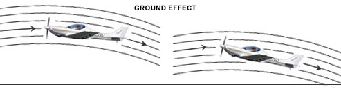
An
aircraft can be flown near the ground or water at a
slightly slower airspeed than at altitude. This is
known as Ground Effect. The airflow around the left
aircraft at altitude can flow around the surface of
the aircraft in a normal manner. The airflow around
the right aircraft is disturbed by the proximity to
the ground. The normal downwash of air produced by
the wing and tail surfaces cannot occur, and the air
becomes compressed under these
surfaces. A "cushioning" effect occurs which allows
the airplane
to fly at slightly slower airspeed than at altitude.
The
maximum ground effect occurs at approximately 1/2
the wingspan above the ground. It is this effect
which causes the plane to seem to float when near
the ground on landing. It also allows the aircraft
to be "pulled" off the ground before adequate climb
speed is achieved.
load factor
The load factor is the total load
supported by the wings divided by the total weight
of the airplane. In straight and level flight, the
load factor is 1; i.e. the weight supported by the
wings is equal to the weight of the loaded aircraft.
The load factor is described as 1G Force. With a
load factor of 1, the G force is 1. In other terms,
the load supported by the wings equals the total
weight of the loaded aircraft.
In a turn, the
weight of the aircraft increases due to the addition
of centrifugal force. The rate of turn determines
the total weight increase. A faster turn (steeper
bank) generates greater centrifugal force. The
centrifugal force is straight out from the centre of
the turn. When the downward weight of the aircraft
is mathematically resolved with the horizontal
centrifugal force, the load on the wings is the
Resultant Load.
banking load factor
In a 45 degree
banked turn, the resultant load factor is
approximately 1.4 G. In other words, the load on the
wings is 1.4 times the loaded weight of the
aircraft. In a 60 degree banked turn, the load
factor is 2G. The load on the wings is TWICE the
loaded weight of the aircraft. The G force is
greater than 1 in a loop manoeuvre for the same
reason; i.e. a centrifugal force adds to the
airplane’s weight. An abrupt change from level to
nose down creates an upward centrifugal force,
decreasing the G load to less than 1G.
The effects of
the bank angle is shown in the graph on the right.
The G Force is shown on the Left Side, and the Bank
Angle is shown on the bottom of the graph.
The manoeuvre
of most importance to the private pilot is the
forces in a turn. The most critical time is in turns
in the traffic pattern, when airspeeds are low, and
the attention to bank angle and airspeed may be
distracted by other
duties.
|
