
taxiway lighting and
markings
The most important rule to
remember is that any sign that has white letters on red is mandatory.
Usually they mark points that must not be passed without permission from
air traffic control.
Taxiways should have
centreline markings
and runway holding position markings whenever they intersect a runway.
Taxiway edge markings are present whenever there is a need to separate
the taxiway from a pavement that is not intended for aircraft use or
to delineate the edge of the taxiway. Taxiways may also have shoulder
markings and holding position markings for Instrument Landing
System/Microwave Landing System (ILS/MLS) critical areas, and
taxiway/taxiway intersection markings.
The
taxiway
centreline is a
single continuous yellow line, 6 inches (15 cm) to 12 inches (30 cm)
in width. This provides a visual cue to permit taxiing along a
designated path. Ideally the aircraft should be kept centred over
this line during taxi to ensure wing-tip clearance.
Taxiway Edge
Markings. Taxiway edge markings are used to
define the edge of the taxiway. They are primarily used when the
taxiway edge does not correspond with the edge of the pavement. There
are two types of markings depending upon whether the aircraft is
suppose to cross the taxiway edge:
1. Continuous
Markings. These consist of a
continuous double yellow line, with each line being at least 6
inches (15 cm) in width spaced 6 inches (15 cm) apart. They are used
to define the taxiway edge from the shoulder or some other abutting
paved surface not intended for use by aircraft.
2. Dashed
Markings. These markings are used when
there is an operational need to define the edge of a taxiway or taxi-lane on a paved surface where the adjoining pavement to the
taxiway edge is intended for use by aircraft. e.g., an apron. Dashed
taxiway edge markings consist of a broken double yellow line, with
each line being at least 6 inches (15 cm) in width, spaced 6 inches
(15 cm) apart (edge to edge). These lines are 15 feet (4.5 m) in
length with 25 foot (7.5 m) gaps. (See FIG 2-3-9.)
Taxi
Shoulder Markings. Taxiways,
holding bays, and aprons are sometimes provided with paved shoulders
to prevent blast and water erosion. Although shoulders may have the
appearance of full strength pavement they are not intended for use by
aircraft, and may be unable to support an aircraft. Usually the
taxiway edge marking will define this area. Where conditions exist
such as islands or taxiway curves that may cause confusion as to which
side of the edge stripe is for use by aircraft, taxiway shoulder
markings may be used to indicate the pavement is unusable. Taxiway
shoulder markings are yellow.
Surface Painted Taxiway Direction Signs. Surface painted
taxiway direction signs have a yellow background with a black
inscription, and are provided when it is not possible to provide
taxiway direction signs at intersections, or when necessary to
supplement such signs. These markings are located adjacent to the
centreline with signs indicating turns to the left being on the left
side of the taxiway centreline and signs indicating turns to the right
being on the right side of the centreline.
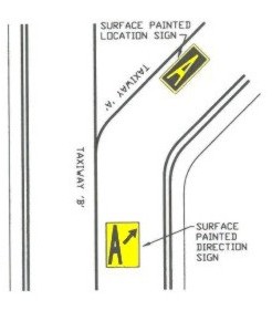
Surface Painted Taxiway Direction Signs
Surface
Painted Location Signs. Surface painted
location signs have a black background with a yellow inscription. When
necessary, these markings are used to supplement location signs
located along side the taxiway and assist the pilot in confirming the
designation of the taxiway on which the aircraft is located. These
markings are located on the right side of the centreline.
Surface Painted
Location Signs
Geographic
Position Markings. These markings are
located at points along low visibility taxi routes designated in the
airport's Surface Movement Guidance Control System (SMGCS) plan. They
are used to identify the location of taxiing aircraft during low
visibility operations. Low visibility operations are those that occur
when the runway visible range (RVR) is below 1200 feet(360m). They are
positioned to the left of the taxiway centreline in the direction of
taxiing. The geographic position marking is a circle
comprised of an outer black ring contiguous to a white ring with a
pink circle in the middle. When installed on asphalt or other
dark-coloured pavements, the white ring and the black ring are
reversed, i.e., the white ring becomes the outer ring and the black
ring becomes the inner ring. It is designated with either a number or
a number and letter. The number corresponds to the consecutive
position of the marking on the route.
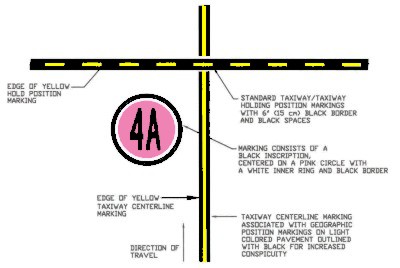
Geographic Position Markings
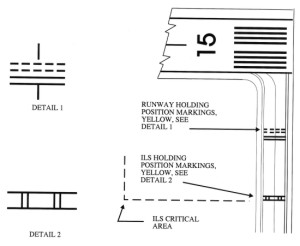
Holding Position Markings
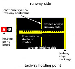
Runway
Holding Position Markings. For runways these
markings indicate where an aircraft is supposed to stop. They consist
of four yellow lines two solid, and two dashed, spaced six or twelve
inches apart and extending across the width of the taxiway or runway.
The solid lines are always on the side where the aircraft is to hold.
There are three locations where runway holding position markings are
encountered.
Runway
Holding Position Markings on Taxiways.
These markings identify the locations on a taxiway where an aircraft
is supposed to stop when it does not have clearance to proceed onto
the runway. When instructed by ATC "Hold short of (runway "xx")" the pilot should stop so no part
of the aircraft extends beyond the holding position marking. When
approaching the holding position marking, a pilot should not cross
the marking without ATC clearance at a controlled airport or without
making sure of adequate separation from other aircraft at
uncontrolled airports. An aircraft exiting a runway is not clear of
the runway until all parts of the aircraft have crossed the
applicable holding position marking.
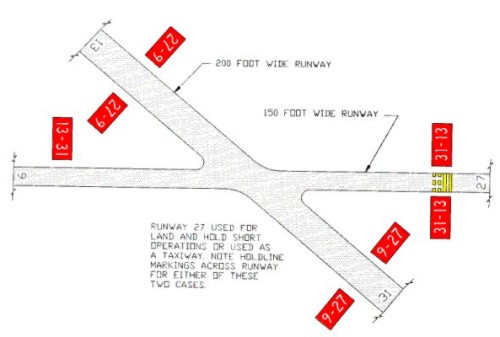
Runway
Holding Position Markings on Runways.
These markings are installed on runways only if the
runway is normally used by air traffic control for "land, hold
short" operations or taxiing operations and have operational
significance only for those two types of operations. A sign with a
white inscription on a red background is installed adjacent to these
holding position markings. (see above) The holding position
markings are placed on runways prior to the intersection with
another runway, or some designated point. Pilots receiving
instructions "cleared to land, runway "xx"" from air traffic control
are authorized to use the entire landing length of the runway and
should disregard any holding position markings located on the
runway. Pilots receiving and accepting instructions "cleared to land
runway "xx," hold short of runway "yy"" from air traffic control
must either exit runway "xx," or stop at the holding position prior
to runway "yy."
Taxiways Located in Runway Approach
Areas.
These markings are used at some airports where it is necessary to
hold an aircraft on a taxiway located in the approach or departure
area of a runway so that the aircraft does not interfere with the
operations on that runway. This marking is collocated with the
runway approach area holding position sign.
Taxiways Located in Runway Approach
Areas
Holding
Position Markings for Instrument Landing System (ILS).
Holding position markings for ILS/MLS critical areas
consist of two yellow solid lines spaced two feet apart connected by
pairs of solid lines spaced ten feet apart extending across the width
of the taxiway as shown. A sign with an inscription
in white on a red background is installed adjacent to these hold
position markings. When the ILS critical area is being protected, the
pilot should stop so no part of the aircraft extends beyond the
holding position marking. When approaching the holding position
marking, a pilot should not cross the marking without ATC clearance.
ILS critical area is not clear until all parts of the aircraft have
crossed the applicable holding position marking.
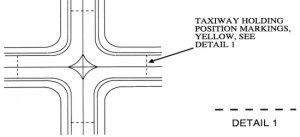
Holding
Position Markings for Taxiway/
Taxiway Intersections.
Holding position markings for taxiway/taxiway intersections consist of
a single dashed line extending across the width of the taxiway as
shown. They are installed on taxiways where air
traffic control normally holds aircraft short of a taxiway
intersection. When instructed by ATC "hold short of (taxiway)" the
pilot should stop so no part of the aircraft extends beyond the
holding position marking. When the marking is not present the pilot
should stop the aircraft at a point which provides adequate clearance
from an aircraft on the intersecting taxiway.
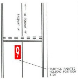
Surface
Painted Holding Position Signs.
Surface
painted holding position signs have a red background with a white
inscription and supplement the signs located at the holding position.
This type of marking is normally used where the width of the holding
position on the taxiway is greater than 200 feet(60m). It is located
to the left side of the taxiway centreline on the holding side and
prior to the holding position marking.
Vehicle Roadway Markings.
The vehicle roadway markings are used when necessary to define a pathway
for vehicle operations on or crossing areas that are also intended for
aircraft. These markings consist of a white solid line to delineate each
edge of the roadway and a dashed line to separate lanes within the edges
of the roadway. In lieu of the solid lines, zipper markings may be used
to delineate the edges of the vehicle roadway.
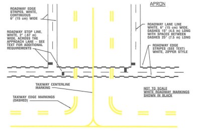
Vehicle Roadway
Markings
Roadway Edge
Stripes, White, Zipper Style
Non-movement
Area Boundary Markings. These markings
delineate the movement area, i.e., area under air traffic control.
These markings are yellow and located on the boundary between the
movement and non-movement area. The non-movement area boundary markings
consist of two yellow lines (one solid and one dashed) 6 inches (15cm)
in width. The solid line is located on the non-movement area side while
the dashed yellow line is located on the movement area side.
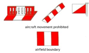
Non-movement
Area Boundary Markings
Airport
Signs
There are six types of signs installed on airfields: mandatory
instruction signs, location signs, direction signs, destination signs,
information signs, and runway distance remaining signs.
Mandatory Instruction Signs
a.
These signs have a red background with a white
inscription and are used to denote:
1.
An entrance to a runway or critical area and;
2.
Areas where an aircraft is prohibited from
entering.
b.
Typical mandatory signs and applications are:
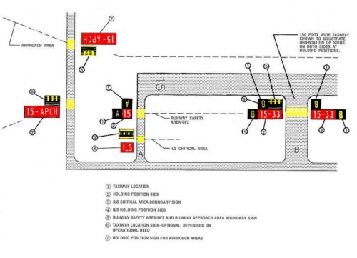
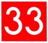
Runway
Holding Position Sign. This sign is
located at the holding position on taxiways that intersect a runway
or on runways that intersect other runways. The inscription on the
sign contains the designation of the intersecting runway as shown in
FIG 2-3-24. The runway numbers on the sign are arranged to
correspond to the respective runway threshold. For example, "15-33"
indicates that the threshold for Runway 15 is to the left and the
threshold for Runway 33 is to the right.

Runway Holding
Position Sign
On taxiways that intersect the beginning of the
takeoff runway, only the designation of the takeoff runway may
appear on the sign, while all other signs
will have the designation of both runway directions.
Holding
Position Sign at Beginning of Takeoff Runway
If the sign is located on a taxiway
that intersects the intersection of two runways, the designations
for both runways will be shown on the sign along with arrows
showing the approximate alignment of each runway. In addition to showing the approximate runway alignment,
the arrow indicates the direction to the threshold of the runway
whose designation is immediately next to the arrow.

Holding
Position Sign for a Taxiway that Intersects
the Intersection of Two Runways
A runway holding
position sign on a taxiway will be installed adjacent to holding
position markings on the taxiway pavement. On runways, holding
position markings will be located only on the runway pavement
adjacent to the sign, if the runway is normally used by air
traffic control for "Land, Hold Short" operations or as a
taxiway.
Runway Approach Area Holding Position Sign.
At some airports, it is necessary to hold an aircraft
on a taxiway located in the approach or departure area for a runway
so that the aircraft does not interfere with operations on that
runway. In these situations, a sign with the designation of the
approach end of the runway followed by a "dash" (-) and letters
"APCH" will be located at the holding position on the
taxiway.
Holding position markings will be located on the taxiway pavement.
An example of this sign is shown below. In this example, the
sign may protect the approach to Runway 15 and/or the departure for
Runway 33.

Holding
Position Sign for a Runway Approach Area
ILS Critical Area Holding Position Sign.
At some airports, when the instrument landing system
is being used, it is necessary to hold an aircraft on a taxiway at a
location other than the holding position described in paragraph
2-3-5, Holding Position Markings. In these situations the holding
position sign for these operations will have the inscription "ILS"
and be located adjacent to the holding position marking on the
taxiway described in paragraph 2-3-5. An example of this sign is
shown below.

Holding
Position Sign for ILS Critical Area
No Entry
Sign. This sign, shown in
below, prohibits an aircraft from entering an area. Typically, this
sign would be located on a taxiway intended to be used in only one
direction or at the intersection of vehicle roadways with runways,
taxiways or aprons where the roadway may be mistaken as a taxiway or
other aircraft movement surface.

Sign
Prohibiting Aircraft Entry into an Area
Location Signs
Location signs are used to identify either a
taxiway or
runway on which the aircraft is located. Other location signs provide
a visual cue to pilots to assist them in determining when they have
exited an area. The various location signs are described below.
Taxiway
Location Sign. This sign has a
black background with a yellow inscription and yellow border as
shown below.

Taxiway
Location Sign
The inscription is the designation of the
taxiway on which the aircraft is located. These signs are installed
along taxiways either by themselves or in conjunction with direction
signs or runway holding position signs.
Taxiway
Location Sign Collocated with
Runway Holding Position Sign

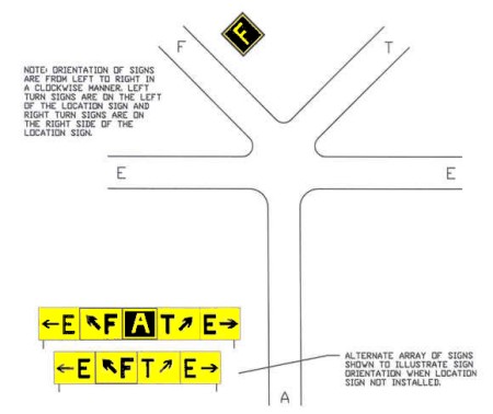
fig 18 Direction Sign
Array with Location Sign
on Far Side of Intersection
Runway
Location Sign. This sign has a
black background with a yellow inscription and yellow border. The inscription is the designation of the
runway on which the aircraft is located. These signs are intended to
complement the information available to pilots through their
magnetic compass and typically are installed where the proximity of
two or more runways to one another could cause pilots to be confused
as to which runway they are on.
Runway Location
Sign
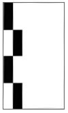
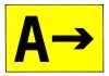
Runway
Boundary Sign. This sign has a
yellow background with a black inscription with a graphic depicting
the pavement holding position marking. This
sign, which faces the runway and is visible to the pilot exiting the
runway, is located adjacent to the holding position marking on the
pavement. The sign is intended to provide pilots with another visual
cue which they can use as a guide in deciding when they are "clear
of the runway."
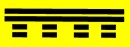
Runway Boundary
Sign
ILS
Critical Area Boundary Sign.
This sign has
a yellow background with a black inscription with a graphic
depicting the ILS pavement holding position marking as shown in FIG
2-3-34. This sign is located adjacent to the ILS holding position
marking on the pavement and can be seen by pilots leaving the
critical area. The sign is intended to provide pilots with another
visual cue which they can use as a guide in deciding when they are
"clear of the ILS critical area."
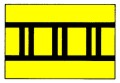
ILS Critical
Area Boundary Sign
Direction Signs
a.
Direction signs have a yellow background with a black
inscription. The inscription identifies the designation(s) of the
intersecting taxiway(s) leading out of the intersection that a pilot
would normally be expected to turn onto or hold short of. Each
designation is accompanied by an arrow indicating the direction of the
turn.
b.
Except as noted in subparagraph e, each
taxiway
designation shown on the sign is accompanied by only one arrow. When
more than one taxiway designation is shown on the sign each
designation and its associated arrow is separated from the other
taxiway designations by either a vertical message divider or a taxiway
location sign as shown in See fig 18.
c.
Direction signs are normally located on the left prior
to the intersection. When used on a runway to indicate an exit, the
sign is located on the same side of the runway as the exit. The
illustration below
shows a direction sign used to indicate a runway exit.
Direction Sign
for Runway Exit
d.
The taxiway designations and their associated arrows on
the sign are arranged clockwise starting from the first taxiway on the
pilot's left.
(See fig 18)
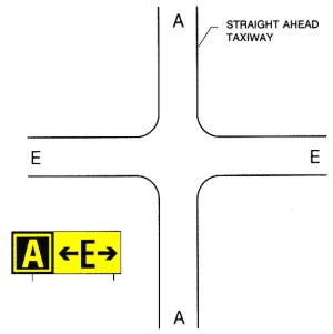
e.
If a location sign is located with the
direction signs, it is placed so that the designations for all turns
to the left will be to the left of the location sign; the designations
for continuing straight ahead or for all turns to the right would be
located to the right of the location sign. (See fig
18)
f.
When the intersection is comprised of only one crossing
taxiway, it is permissible to have two arrows associated with the
crossing taxiway as shown below. In this case, the location
sign is located to the left of the direction sign.
Direction Sign
Array for Simple Intersection
Destination Signs
Destination signs also have a yellow background with a
black inscription indicating a destination on the airport. These signs
always have an arrow showing the direction of the taxiing route to
that destination. The illustration below is an example of a typical destination
sign. When the arrow on the destination sign indicates a turn, the
sign is located prior to the intersection.

Destination Sign for Military Area
Destinations commonly shown on these types of signs
include runways, aprons, terminals, military areas, civil aviation
areas, cargo areas, international areas, and fixed base operators. An
abbreviation may be used as the inscription on the sign for some of
these destinations.
When the inscription
for two or more destinations having a common taxiing route are placed
on a sign, the destinations are separated by a "dot" (·) and one arrow
would be used as shown below.
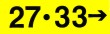
Destination
Sign for Common Taxiing Route
to Two Runways
When the inscription
on a sign contains two or more destinations having different taxiing
routes, each destination will be accompanied by an arrow and will be
separated from the other destinations on the sign with a vertical
black message divider as shown below.
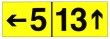
Destination
Sign for Different Taxiing Routes
to Two Runways
Information Signs
Information signs have a
yellow background with a black inscription. They are used to provide the
pilot with information on such things as areas that cannot be seen from
the control tower, applicable radio frequencies, and noise abatement
procedures. The airport operator determines the need, size, and location
for these signs.
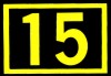
Runway Distance Remaining Signs
Runway distance remaining
signs have a black background with a white numeral inscription and may
be installed along one or both side(s) of the runway. The number on the
signs indicates the distance (in thousands of feet) of landing runway
remaining. The last sign, i.e., the sign with the numeral "1," will be
located at least 950 feet from the runway end. The illustration below shows an
example of a runway distance remaining sign.

Runway Distance
Remaining Sign Indicating
3,000 feet of Runway Remaining
Taxiway
Lighting
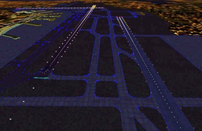
Philadelphia International Airport. The white lighting of the 3 runways is
clearly visible, while the taxiways are lit in blue.
Taxiway Edge Lights.
Taxiway edge lights
are used to outline the edges of taxiways during
periods of darkness or restricted visibility
conditions. These fixtures emit blue light.
NOTE-
At most major airports these lights have variable
intensity settings and may be adjusted at pilot
request or when deemed necessary by the controller.
Taxiway Centreline Lights.
Taxiway
centreline lights are used to facilitate ground
traffic under low visibility conditions. They are
located along the taxiway centreline in a straight
line on straight portions, on the centreline of curved
portions, and along designated taxiing paths in
portions of runways, ramp, and apron areas. Taxiway
centreline lights are steady burning and emit green
light.
Clearance Bar Lights.
Clearance bar lights are installed at holding
positions on taxiways in order to increase the conspicuity of the holding position in low visibility
conditions. They may also be installed to indicate the
location of an intersecting taxiway during periods of
darkness. Clearance bars consist of three in-pavement
steady-burning yellow lights.
Runway
Guard Lights. Runway guard lights
are installed at taxiway/runway intersections. They
are primarily used to enhance the conspicuity of
taxiway/runway intersections during low visibility
conditions, but may be used in all weather conditions.
Runway guard lights consist of either a pair of
elevated flashing yellow lights installed on either
side of the taxiway, or a row of in-pavement yellow
lights installed across the entire taxiway, at the
runway holding position marking.
NOTE-
Some airports may have a row of three or five
in-pavement yellow lights installed at taxiway/runway
intersections.
Stop
Bar Lights.
Stop bar lights, when installed, are used to confirm
the ATC clearance to enter or cross the active runway
in low visibility conditions (below 1,200 ft Runway
Visual Range). A stop bar consists of a row of red,
unidirectional, steady-burning in-pavement lights
installed across the entire taxiway at the runway
holding position, and elevated steady-burning red
lights on each side. A controlled stop bar is operated
in conjunction with the taxiway centreline lead-on
lights which extend from the stop bar toward the
runway. Following the ATC clearance to proceed, the
stop bar is turned off and the lead-on lights are
turned on. The stop bar and lead-on lights are
automatically reset by a sensor or backup timer.
CAUTION-
Pilots should never cross a red illuminated stop bar,
even if an ATC clearance has been given to proceed
onto or across the runway.
|
