
altimeter
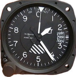
The sensitive
altimeter is the cockpit instrument that indicates the aircraft's altitude. The
instrument is a refined aneroid barometer with a dial indicating height above a
pre-set level rather than atmospheric pressure. The main component of such
instruments is a small, flexible, corrugated metal capsule, from which the air
has been partially evacuated, fitted with a metal closure or diaphragm. There is
a spring within the capsule, that applies a constant force to the bottom of the
diaphragm, while atmospheric static pressure applies a counter force to the top,
so that the diaphragm moves as atmospheric pressure changes. The movement of the
pressure sensing capsule is transferred and magnified, via a mechanical linkage
or piezo-quartz component, to a dial pointer or pointers, or a digital display,
which indicate the altitude reading. The static pressure is drawn from the
aircraft's static vent, which may induce slight position errors due to
aerodynamic effects around the vent.
The level in the atmosphere at which any particular pressure occurs is also
dependent on temperature – as we saw in the airspeed and air properties module –
but the altimeter does not sense the air temperature. Consequently all
altimeters are calibrated in accordance with the International Standard
Atmosphere model, which utilises a standard temperature lapse rate with height
of 6.5 °C per km. The atmosphere in any region rarely corresponds to the ISA, so
aneroid altimeters do not present a totally accurate height indication. This is
not that important as true altitude can be calculated, in the rare circumstance
that it is needed for terrain clearance purposes: there is no problem with air
traffic management, in that all aircraft in the same region, with properly set
(and functioning) altimeters, will be out by the same amount.
It is, of course, desirable to set the current local surface pressure into the
altimeter by setting that reference pressure into a pressure-setting scale (known
since the 1930s as the 'Kollsman Window'), which in turn resets the position
of the height indicating pointers against the dial. Or, if the aircraft is on
the ground, the same result is achieved by turning the pressure-setting scale
until the altimeter indicates the known airfield elevation.
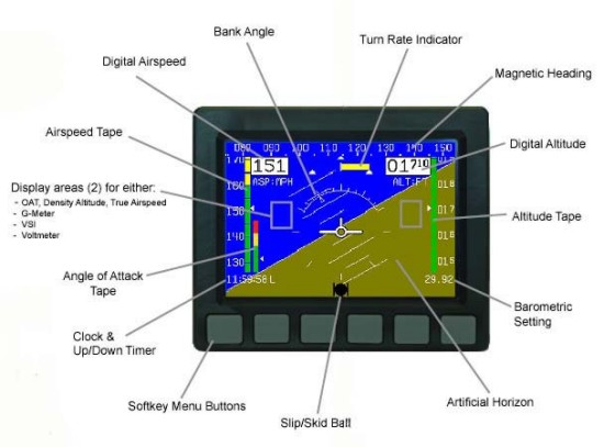
Electronic altimeter
Electronic flight instrument systems [EFIS] use
solid state electronic components as sensors plus software to display the usual
flight instrument readings on a liquid crystal screen. In such systems the
atmospheric static pressure is fed to a pressure transducer which senses and
convert pressures to voltages. Note that the EFIS has an outside air temperature
probe and the software can calculate density altitude when needed.
Electronic altimeters are also available as single panel instruments or possibly
combined with an ASI function.
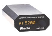
Altitude encoding
In some flight conditions an
aircraft must operate a transponder for traffic separation purposes. The
transponder obtains altitude data from a special altitude encoding altimeter or
from a blind encoder; the latter being an electronic device which obtains
current atmospheric pressure from the static pressure line and the reference
pressure used is preset at 1013.2 hPa. That same reference pressure is used for
the altitude encoding function of the altimeter, thus the transponder broadcasts
pressure altitude only.
inherent errors
The
pneumatic altimeter is subject to the following errors:
a) Position Error: In some installations, position error can be of
considerable magnitude.
b) Scale Error: Commonly referred to as instrument error, scale
error is caused by the aneroids not assuming the precise size designed for a
particular pressure difference. This error is irregular throughout the range of
the instrument (it might be -30 feet at 1,000 feet and +50 feet at 10,000 feet).
The tolerances for this error became larger as the measured altitude is
increased.
c) Mechanical Error: Mechanical error is caused by misalignment or
slippage in the gears and linkage connecting the aneroids to the display, or in
the shaft of the barosetting knob.
d) Density Error.- ICAO Standard Atmosphere conditions seldom
prevail, and the resulting density error is only partially offset by the
diligent application of correct altimeter settings (station or standard
pressure). It can generally be disregarded for Air Traffic Control purposes,
since all pressure altimeters in close proximity react in the same way, and
vertical separation is maintained.
e) Hysteresis: This error is a lag in the altitude indications
caused by the elastic properties of the materials used in the aneroids. It
occurs when an aircraft initiates a large, rapid altitude change or an abrupt
level-off from a rapid climb or descent. It takes a period of time for the
aneroids to catch up with the new pressure environment; hence, a lag in
indications. This error has been significantly reduced in modern altimeters and
is considered negligible at normal rates of descent for jet aircraft.
f) Reversal Error: During abrupt or rapid attitude changes, reversal
error occurs; it is only momentary in duration.
Altimeter indicated altitude: the approximate
height of the aircraft above mean sea level [amsl], calculated in
accordance with ISA.
Calibrated altitude: the indicated altitude corrected for
internal instrument error and static vent position error.
Density altitude: a calculation used to determine possible
aircraft performance – see the 'high density altitude' section below.
The pressure altitude adjusted for variation from standard temperature,
or, the height in ISA having a density corresponding to the location
density, then called density height.
Pivotal altitude: is not associated with altimeter setting, it is
a term used by the proponents of 'ground reference' manoeuvres such as 'eights
on pylons'. It is a particular height above ground at which, from
the pilot's outlook, the extended lateral axis line of an aircraft doing
a 360° level turn [in nil wind conditions] would appear to be fixed to
one ground point, and the aircraft's wingtip thus pivoting on that
point. The pivotal altitude in nil wind conditions is easily calculated
by squaring the TAS in knots and dividing by 11.3. So an aircraft
circling at 80 knots would have a pivotal altitude around 550 feet. no
matter what the bank angle.
When an aircraft is turning at a height greater than the pivotal
altitude the wingtip appears to move backwards over the landscape. When
an aircraft is turning at a height less than pivotal altitude [i.e.
usually close to the ground] the wingtip appears to move forward over
the landscape.
Pressure altitude: the altimeter reading when the
pressure-setting scale is set to 1013.2 hPa, the ISA Standard
Pressure altimeter setting [QNE see below], sometimes termed
pressure height. All aircraft cruising in the Standard
Pressure Region, above a transition layer which commences
at 10 000 feet, use QNE and the subsequent altimeter reading is normally
referred to as flight level [FL]. However an aircraft maintaining
a constant altitude using QNE, or any other fixed setting for that
matter, is following an isobaric surface whose height amsl will vary
according to atmospheric conditions. An aircraft maintaining FL145 [i.e.
14 500 feet], and flying towards a lower pressure area, will actually be
descending at a rate approximating 40 feet per one hPa decrease in
surface level pressure.
True altitude: the calibrated altitude corrected for atmospheric
temperature conditions. But as the correction will assume standard
pressure and temperature lapse rates between the surface and the
aircraft level, it will not be an accurate reflection of the aircraft's
height above mean sea level. And remember if you maintain a particular
altitude you will be following an isobaric surface and not maintaining a
constant height. The only way to measure height accurately is by
triangulation – and that can only be done by a GPS receiver in the
aircraft. However there are still problems in determining the vertical
datum.
Q-codes
Note: the letters in the Q-code nomenclature have no
literal significance, these are remnants of an extensive notation system from
the days of wireless-telegraphy.
QFE: the barometric pressure at the station location or aerodrome
elevation datum point. If QFE is set on the altimeter pressure-setting scale
while parked at an airfield, the instrument should read close to zero altitude
– if the local pressure is close to the ISA standard for that elevation.
However the use of QFE is deprecated.
QFF: the mean sea level [msl] pressure derived from the
barometric pressure at the station location by calculating the weight of an
imaginary air column, extending from the location to sea level, assuming the
temperature and relative humidity at the location are the long term monthly
mean, the temperature lapse rate is ISA and the relative humidity lapse rate
is zero. This is the Australian Bureau of Meteorology method; QFF calculations
differ among meteorological organisations. QFF is the location value plotted
on surface synoptic charts and is closer to reality than QNH, though it is
only indirectly used in aviation.
QNH: the msl pressure derived from the barometric
pressure at the station location by calculating the weight of an imaginary air
column, extending from the location to sea level, assuming the temperature at
the location is the ISA temperature for that elevation, the temperature lapse
rate is ISA and the air is dry throughout the the column.
The Australian aviation regulations state that when an 'accurate' QNH is set
on the pressure-setting scale at an airfield, the altimeter indication should
read within 100 feet of the published airfield elevation, or 110 feet if
elevation exceeds 3300 feet; otherwise the altimeter should be considered
unserviceable. However due to the inherent inaccuracy possible in QNH, this
may not be so. The difference between QFF and QNH when calculated on a hot day
at a high airfield in Australia can be as much as 4 hPa, equivalent to about
120 feet. The advantage to aviation in using the less realistic QNH is that
all aircraft altimeters in the area will be out by about the same amount, and
thus maintain height interval separation.
The Local QNH at an airfield is normally derived from an actual
pressure reading, but the Area QNH used outside the airfield zone is a
forecast value, valid for three hours, and may vary by up to 5 hPa from any
Local QNH in the same area. Either Local QNH or Area QNH may be set on the
altimeter pressure-setting scale of all aircraft cruising in the
Altimeter Setting Region; which extends from the surface to the
(Australian) Transition Altitude of 10 000 feet. The cruising levels
within the Altimeter Setting Region are prefixed by 'A' e.g. A065 = 6500 feet
amsl.
When there is no official Local QNH available at an airfield, and the site
elevation is known, the Local QNH can be derived by setting the subscale (when
the aircraft is on the ground of course) so that the altimeter indicates the
known airfield elevation. The use of Local QNH is important when conducting
operations at an airfield as the circuit and approach pattern is based on
determining height above ground level [agl].
Note that it is not mandatory for VFR aircraft to use the area QNH whilst
enroute. You may substitute the current local QNH of any aerodrome within 100
nm of the aircraft or the local QNH at the departure airfield.
The purpose of the transition layer is to maintain a separation zone
between the aircraft using QNH and those using standard pressure. If Area QNH
was 1030 hPa there would be about 500 feet difference displayed between
setting that value and setting standard pressure. The transition layer extends
from the Transition Altitude to the Transition Level which is usually
at FL110 but it may extend to FL125 – depending on mean sea level pressure.
QNE: is the ISA Standard Pressure altimeter setting of 1013.2
hPa. The term QNE is now rarely encountered but if you set 1013.2 on the
altimeter pressure-setting scale while parked the altimeter will indicate the
current ISA pressure altitude of the airfield – which is the first step in
calculating density altitude. QNE is also the standard factory setting for
altitude encoding.
radar altimeter
For the serious IFR pilot, when it comes to landing at a strange
airport in poor conditions, nothing can compare to the security a radar
altimeter can provide. Only a radar altimeter can give you absolute assurance of
your height above the ground.
All radar altimeters have three basic components, an antenna, a
receiver transmitter, and an indicator.
Antenna
The antenna can come in different types depending on where you decide to mount
it on a flat or skewed area under the fuselage. Antennas are designed
specifically for each system, so changing the unit also involves changing the
antenna.
Receiver Transmitter
The core of the device, a radar altimeter actually is a single frequency radar
system that broadcasts a pulsed tone directly downward. The time it takes for
the reflected tone to be received directly translates into your height above
the terrain. Clearly, the better the Receiver Transmitter, the more accurate
your readings will be.
Indicators
All models allow you to select a decision height (DH) altitude or any other
altitude to about 2,500 feet above the ground. When you descend to this preset
altitude a visual and aural warning will sound. Some models use electronic
digital displays and others use the more common analogue (dial) displays. The
indicator you choose depends on whether you have the required panel space for
a 3 inch analogue type or if you prefer a smaller size. A few indicators and
units offer some additional features and are all digital models.
altitude alerting systems
An altitude alerting
system works with altimeter data. The desired level-off altitude is set on the
altitude selector during a climb or descent.
The pilot is alerted by aural or visual signals upon approaching the
prescribed altitude in sufficient time to establish level flight at that
preselected altitude (usually 1,000 ft. above or below the selected altitude).
|
