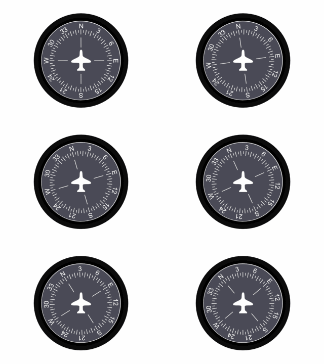
Because the heading indicator has no direction-seeking
qualities of its own, it must be set to agree with the magnetic compass. This
should be done only on the ground or in straight-and-level, unaccelerated flight
when magnetic compass indications are steady and reliable.
The pilot should set the heading indicator by turning the heading indicator
reset knob at the bottom of the instrument to set the compass card to the
correct magnetic heading.

The pilot of a light aircraft should check the heading
indicator against the magnetic compass at least every 15 minutes to assure
accuracy. Because the magnetic compass is subject to certain errors , the pilot
should ensure that these errors are not transferred to the heading indicator.
The operation of the heading indicator depends upon the principle of rigidity
in space of a universally mounted gyroscope. The rotor turns in a vertical
plane. Fixed at right angles to the plane of the rotor (to the vertical gimbal)
is a circular compass card. Since the rotor remains rigid in space, the points
on the card hold the same position in space relative to the vertical plane. As
the instrument case revolves about the vertical gimbal, the card provides clear
and accurate heading references.
The source of power for the gyro is the engine-driven vacuum
pump (or venturi) which sucks air from the rear of the instrument case. This
causes air under atmospheric pressure to pass through the filtering system,
thence through an air bearing into the hollow vertical gimbal ring. The air then
passes through the air nozzle and jets, striking the rotor at a point just above
the plane of the horizontal gimbal.
The speed of the rotor may vary from 10,000 to 18,000 rpm,
depending on instrument design. For proper operation, the suction gauge reading
can be as low as 3.5 and as high as 5.0 inches of mercury, with 4.0 the desired
suction. Limits for adjustment of the vacuum are 3.75 and 4.25, or as specified
in your aircraft operating hand-book.
erecting
mechanism
During flight, precessing forces displace the rotor from the
vertical plane. To compensate for precession and to provide better airflow
distribution against the rotor buckets, the air is divided by two parallel jets
at the tip of the nozzle.
Each jet strikes the buckets at points equidistant from the centre of the
buckets when the rotor is perpendicular in its normal rotating plane. When the
gyro precesses, both jets strike one side of the buckets and cause the plane of
the rotor to again become parallel to the flow of air from the jets.
limitations
The design of the vacuum-driven directional gyro imposes
limitations on rotation about the gimbals preventing operation of the instrument
in abnormal flight attitudes. If the plane of rotation of the rotor were able to
become parallel to the base of the case, it would lose its ability to hold the
card in a stationary position, since its axis would be in line with the vertical
gimbal and the card would tend to spin with the rotor. The stop, or limiting
factor, in the instrument is the caging arm. In the uncaged position, the caging
arm rests on the bottom of the vertical gimbal ring and in that position
restricts the movement of the vertical gimbal ring about the rotor or the
horizontal gimbal.
The caging arm is held against the bottom of the vertical
gimbal ring by means of a small spring so that rough air cannot cause it to fly
up and tumble the instrument. Beyond the normal operating limits - 55° of pitch
and bank - when the horizontal gimbal touches the stop, the precessional force
causes the card to spin rapidly. This may be corrected by caging, resetting, and
uncaging the instrument.
errors
The chief cause of precession, causing the card to creep or
drift, is bearing friction. Normal movement of the gimbal rings produces
friction, which is increased if the bearings are worn, dirty, or improperly
lubricated. Other sources of precession error include unbalanced gyro components
and the effect of the earth's rotation. The latter effect depends upon the
position of the instrument in relation to the earth, and is not appreciable
unless a flight involves considerable change in latitude.
An apparent error frequently results from misuse of the magnetic compass when
the directional gyro is set. Unless magnetic deviations are applied, the
indicator may appear to drift several degrees after a turn is completed. Another
common error results from failure to maintain straight-and-level flight while
reading the magnetic compass for the heading to set in the directional gyro.
Errors in the magnetic compass induced by attitude changes are thus duplicated
in the heading indicator.
The instrument should be checked at least every 15 minutes during flight and
reset to the correct heading. An error of no more than 3° in 15 minutes is
acceptable for normal operations.
caging mechanism
The heading indicator can be adjusted by pushing in on the
caging knob to mesh pinion and ring gears, thereby permitting rotation of the
vertical gimbal and card. (Another type of caging mechanism utilizes friction
between rubber and metal rings.) After setting, the gyro is uncaged by pulling
out the caging knob to release the gimbals from the caging mechanism. Before
setting the instrument during ground operations, allow 5 minutes after engine
starting for the gyro to reach operating speed.
