Most aircraft have several instruments that are traditionally
driven by mechanical Gyros. These instruments assist in flying and navigation of
an aircraft. These instruments are the Attitude Indicator (also known as the
Vertical Gyro), the Directional Gyro, and the Turn and Bank Indicator. Aircraft
also typically have a compass, and in some cases a Flux Valve (also known as a
Magnetometer) to which the Directional Gyro is connected or slaved to cancel
long term drift. If the aircraft does not have an electronic Flux Valve, then
the Directional Gyro or DG has to be manually reset to the compass reading
during straight and level flight (when the compass is accurate) on a periodic
basis. In most light aircraft the Turn Coordinator (TC) is electrically
driven. Usually the Heading Indicator (HI) and Attitude Indicator (AI) are
vacuum driven.
The three Gyro instruments, Attitude Indicator, Directional
Gyro and Turn and Bank Indicator are ‘gyro’ driven. What does gyro-driven mean?
A gyro is a spinning wheel (mass) that obeys the Laws of Physics. The spinning
wheel is spun up either electrically (electric gyros) or via air flow (vacuum
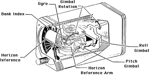
gyros) to high rotational speeds and a high angular momentum. The spinning wheel
is mechanically isolated from the casing of the instrument thru a series of
gimbals. Due to the conservation of angular momentum, the spinning wheel will
try to maintain its orientation, via the gimbals, as the outer casing moves. The
outer casing is of course connected to the airframe. The gimbals, move by the
amount the aircraft has rolled, pitched, or changed heading, and in some cases
directly connect to the display. The display provides an indication of the
aircraft attitude. In the case of a remote gyro and also with many electric
gyros, the gimbals provide an analogue electrical output proportional to
aircraft orientation change.
gyroscopic
principles
Any spinning object possesses gyroscopic characteristics. The
central mechanism of the gyroscope is a wheel similar to a bicycle wheel. It's
outer rim has a heavy mass. It rotates at high speed on very low friction
bearings. When it is rotating normally, it resists changes in direction.
The gyroscope exhibits two predominant characteristics:
-
Rigidity in Space
-
Precession
rigidity in
space
The gyroscope resists turning. When it is "gimballed" ( free
to move in a given direction) such that it is free to move either in 1, 2 or 3
dimensions, any surface such as an instrument dial attached to the gyro assembly
will remain rigid in space even though the case of the gyro
turns. The Attitude Indicator (AI) and the Heading
Indicator (HI ) use this property of rigidity in space for
their operation. The HI responds only to change of heading.
The AI responds to both changes in Pitch and in Roll.
precession
Precession is the deflection of a spinning wheel 90 ° to the
plane of rotation when a deflective force is applied at the rim. If a force is
applied the top of the rim (the plane of rotation), the precession (turn) will
be 90° in the horizontal plane to the left. The Turn Coordinator (TC)
uses this precession property. For example, then taxiing on the ground, the Turn
Coordinator will move, with the small airplane in the instrument showing a bank,
even though the aircraft is level. The banking of the small aircraft
presentation indicates only that the aircraft is turning.
the vacuum
system
The Attitude Indicator (AI) and the
Heading Indicator (HI) in light aircraft are usually driven by a vacuum
system. The principal components are shown below. Not shown are auxiliary
devices such as valves, filters etc. A pump provides the vacuum to the AI and HI
through a system of vacuum lines. A Vacuum Gauge is attached to the lines which
gives the pilot an indication that adequate vacuum is being generated.
gyro power sources
Air or electricity supply the power to operate gyro instruments in light
aircraft. If the directional indicator and attitude indicator are air-driven (as
they generally are), the turn-and-slip indicator is electrically powered. The
advantage of this arrangement is that if the vacuum system (which supplies air)
fails, the instrument pilot still has the compass and the turn indicator for
attitude and direction reference, in addition to the pitot-static
instruments.
1. vacuum power system: Air-driven gyros normally are powered by a vacuum
pump attached to and driven by the engine. Suction lines connect the pump to the
instruments, drawing cabin air through the filtered openings in the instrument
case. As the air enters the case, it is accelerated and directed against small
"buckets" cast into the gyro wheel. A regulator is attached between the pump and
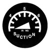
the gyro instrument case to control suction pressure. There is normally a vacuum
gauge, suction gauge (See the Typical Suction Gauge figure,
below) or warning light. Because a constant gyro speed is essential for
reliable instrument readings, the correct suction pressure is maintained with a
vacuum pressure regulator.
The air is drawn through a filter, to the instruments and then to the pump
where it is vented to atmosphere. The pilot should consult the aircraft
operating manual for specific information with regard to vacuum system normal
operating values. Low gyro rotation speeds cause slow instrument response or
lagging indications, while fast gyro speeds cause the instruments to overreact
in addition to wearing the gyro bearings faster and decreasing gyro life.
2. electrical power system: An electric gyro, normally used to drive the turn
coordinator or turn-and-slip indicator, operates like a small electric motor
with the spinning gyro acting as the motor armature. Gyro speed in these
instruments is approximately 8,000 rpm.
Aircraft that normally operate at high altitudes do not use a vacuum system
to power flight instruments because pump efficiency is limited in the thin, cold
air. Instead, alternating current (a.c.) drives the gyros in the heading and
attitude indicators. The a.c. power is provided by inverters that convert direct
current to alternating current. In some cases, the a.c. power is supplied
directly from the engine-driven alternator or generator.