WHAT'S AN HSI?
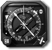
An HSI, or Horizontal Situation Indicator, is a combination of two familiar
cockpit instruments: the directional gyro with a heading bug and a VOR/ILS
indicator.
WHAT DOES AN HSI DO FOR THE PILOT?
Combining the directional gyro and the NAV indicator into one instrument
reduces pilot workload by providing heading, course reference, course deviation
and glide slope information - all in one visual aid. In addition, an HSI makes
it easier to visualize the aircraft's position with reference to the selected
course or holding patterns. The "split needle" presentation made up of the
course and reciprocal pointers and the VOR/LOC deviation indicators, clearly
shows both selected course and course deviation.
It also gives standard sensing and course deviation indication on back course
ILS approaches provided the front course heading is set under the head of the
course pointer and you fly toward the course deviation indicator. Provides
convenient 45° tic marks to help visualize procedure turns and reciprocals so
that pilots need not memorize outbound/inbound headings or add/subtract 45° for
intercepts or offsets. The HSI provides a heading bug for autopilot coupling or
as a heading reminder in aircraft not equipped with autopilots.
Heading Select Knob
Rotating this knob sets the heading bug and will also align a heading
transformer for coupled autopilot use, to the selected heading. Pulling this
knob out will cage the gyro.
Heading Flag
This red warning flag indicates loss of electrical power to the gyro. Heading
information is then unusable but all course information (comparable to a
standard VOR/ILS) remains valid.
Course Select Knob
Rotating this knob sets the course pointer to a selected course, and if so
equipped, a course transformer for coupled autopilot use.
Course Pointer
This pointer indicates the selected course. Turning the course select knob
will rotate the course pointer, VOR/LOC deviation indicator, and course
reciprocal around the compass card. As the aircraft's heading changes, the
course pointer will rotate with the compass card to indicate the difference
between the course, under the course pointer, and the actual aircraft heading,
under the lubber line. The course selector may also be coupled to an autopilot
or flight director. When coupled, "off course" signals will be generated which
direct the autopilot to maintain or acquire the selected course.
VOR/LOC Deviation Indicator
The centre portion of the course pointer needle moves to indicate deviation
from selected course. A series of "dots" provides a linear indication of how far
the aircraft is "off course." In VOR use, each dot represents 5 degrees; when
being used to fly the localizer, it shows 1 1/4 degrees per dot; for RNAV "APPR"
mode, 0.625 nm per dot; and for RNAV "Enroute" mode it indicates 1.25 nm per
dot. An "on course" condition is indicated when the course pointer, the course
deviation bar, and the course reciprocal are all "in line."
To-From Indicator
This indicator is a white triangle and appears underneath the VOR/ILS
deviation indicator. It shows whether the selected course will take the aircraft
either TO or FROM the VOR station.
Reference Aircraft
Representing the actual aircraft, this symbol is fixed and is located "in
line" with the lubber line.
Lubber Line
This orange line, located at the top of the display, indicates the aircraft's
magnetic heading on the compass card. The lubber line is "in line" with the
reference symbol to reinforce this association.
Compass Card
This card, located beneath the lubber line, indicates the aircraft's current
heading. The card is mechanically coupled to the compass card set knob and, at
the start of each flight, must be set by the pilot to agree with the magnetic
compass heading. As the flight progresses and headings change, the directional
gyro rotates the card to indicate the current heading. As with any standard
unslaved DG, some gyro precession will occur. Therefore, it is necessary to
check and reset the compass card at periodic intervals.