traffic alert and
collision avoidance system (TCAS)
Two models of TCAS exist today for air carriers or aircraft owners and
operators. Both TCAS systems are transponder based. If a nearby aircraft has a
transponder that is not functioning or is in the "OFF" position, then the TCAS
system will not detect the threat aircraft. Three basic components make up the
TCAS systems. The first in the antenna system; the second the TCAS processor;
and the third component is the instrument panel display.
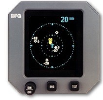
TCAS I provides three levels of alert. The first level of alert is indicated
on the display as an open diamond shape, with the altitude separation indicated
between the host and threat aircraft and an arrow indicating if the threat
aircraft is climbing, descending, or at the same altitude.
This is referred to as Other Traffic (OT). OT is not an immediate threat but
is within the surveillance area and the pilot should be aware of existing
traffic.
The second level of alert is Proximity Alert (PA) and is displayed with the same
information as OT, with the exception that the diamond shape is now a solid
shape on the traffic display. Both OT and PA alerts are white on a colour
display or are not highlighted on a monochromatic display.
Traffic with a calculated intercept course for altitude and direction become
a Traffic Alert (TA). When a TA is encountered, the intruder traffic is
indicated as an orange colour circle, or becomes highlighted on a monochromatic
display. The pilot is also alerted by an automated voice alert that says
"Traffic, Traffic!"
This aural alert diverts the pilot’s attention to the panel mounted display
to ascertain the location of the threat alert, determine the degree of threat,
and decide what action may have to be taken to avert a mid-air collision. The
alert is based on time to closure rate. The maximum alert is 30 seconds at a
maximum 1,200-knot closure, which calculates to a ten mile distance.
TCAS II provides a similar level of alerts as the TCAS I with the addition of
Resolution Advisories (RA). When the TCAS II system detects an imminent
intercept course, the instrument panel display changes the intruder aircraft to
a red colour circle and the pilot is instructed by the TCAS II system to "Climb"
or "Descend" by the voice alerter to avert a mid air collision. Both aircraft
must be equipped with TCAS II systems to experience Resolution Advisories.
TCAS I system
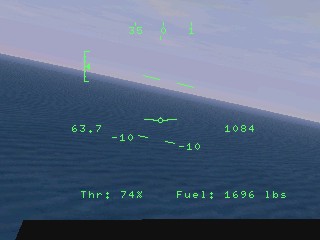
head-up display (HUD)
The head up display (HUD) was originally developed for use in the 1960s for
combat aircraft. Today HUDs are also available in commercial aircraft. Cockpit
displays were traditionally head down displays (HDD). These displays are mounted
on an instrument panel below the level of the wind screen (wind shield) and
pilots have to take their eyes off the outside environment and lower and refocus
their vision to read the meters, dials and indicators. As aircraft became more
sophisticated and electronic instrument landing systems (ILS) were developed in
the 1930s and 1940s, it was necessary while landing in poor weather for one
pilot to monitor the instruments to keep the aircraft aligned with radio beams
while a second pilot watched out side of the windows to quickly take control of
the aircraft as soon as the runway appeared through the weather. This is still
the standard practice used for passenger carrying aircraft in commercial service
while making ILS landings. As single piloted aircraft became more complex, it
became very difficult for pilots to perform the workload. To overcome this
problem the head up display (HUD) was developed in the 1960s by a number of
companies. HUDs enable a pilot to monitor the external environment while
simultaneously being able to monitor key instruments and information presented
in their field of vision (FOV). The HUD information is also focused at infinity
so that the pilots need not refocus their eyes while monitoring both the
external world and the instruments.
Typical HUDs project information from a bright cathode ray tube (CRT) mounted
vertically in the instrument panel. These CRTs project light upward onto the
surface of a nearly transparent glass plate through which the pilot also
continues to see the outside world. Most often this transparent glass
plate is placed in between the pilot and the wind screen and is tilted toward
the pilot at about a 45 degree angle.
More recently helmet integrated displays (HID) have been developed so that the
users can read instruments while turning their heads to view the world. In these
systems one or two miniature CRTs are usually mounted inside of the helmet over
the pilot’s ears and project forward to reflect off the inner surface of the
helmet face plate back into the pilot’s eyes.
Two CRT or liquid crystal display (LCD) systems (one for each eye) are being
developed to provide 3D stereoscopic display of information to the pilot.
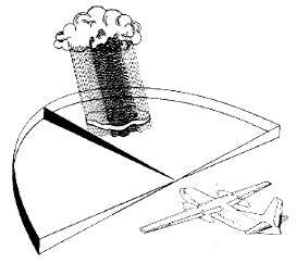
weather radar
The conical beam of the weather radar sweeps up targets left
and right of the aircraft centreline. This positions the azimuth of the storm
area, and that position is incorporated with the distance to “paint” a two
dimensional image on the screen. Through the tilt control knob, the pilot can
better examine the storm in the vertical, relating various degrees of
precipitation to the aircraft’s current level. The tilt knob is arguably the
most important control function available to the pilot. Tilt knob use is
essential if ground returns are not to be painted at differing aircraft
attitudes and altitudes.
Radar provides slices of storm characteristics
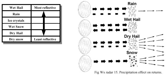
When radar energy encounters a precipitation particle some of
the energy is absorbed, some returns to the receiver, and some is scattered in
various directions. Different types of precipitation have widely differing rates
of reflectivity. Weather radar does NOT detect non rain bearing cloud, fog, or
clear air turbulence (CAT). It does detect wet hail and large raindrops very
well. A large amount of microwave energy is reflected by wet hail and large
raindrops, whereas dry snow does not reflect energy, scattering it instead,
mainly away from the receiver.
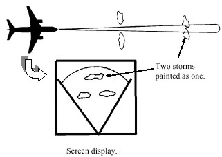
Beamwidth
This describes degrees between the edges of the beam. At 60 nm distance from
aircraft a 3 degree beamwidth is 3nm across, and at 120 nm it is 6 nm across.
This can lead to two distant storms that are close together being painted as one
large storm. As the aircraft gets closer to the storms, they eventually resolve
into two separate storms, once the distance between them is greater than the
beamwidth at that range.
Beamwidth can effect storm resolution.
stormscope
Stormscopes are ultra sensitive receivers set up to display
electrical discharges. When a lightening bolt releases it's energy it sends out
a signal at a frequency that the stormscope is set up to receive. It then
measures that signal for strength and duration in order to display proper
distance information. The antenna (usually mounted on the bottom of the
aircraft) has coils that cross each other at a 90-degree angle. When a strike is
received the antenna senses the direction by feeling which part of the coil had
the strongest pulse.
mode 'S' transponder
The Mode S (S for Select) Transponder has been designed as an
evolutionary addition to the Air Traffic Control Radar Beacon System (ATCRBS) to
provide the enhanced surveillance and communication capability required for Air
Traffic Control (ATC) automation. While providing the usual 4096 Identification
Code and pressure altitude information to ATC interrogation, Mode S also
provides for selective interrogation to enhance surveillance functions and data
link communication functions.
Mode S performs all the functions of Mode A and C
transponders, and has data link capability. Mode S transponders are an integral
component of all Traffic Alert and Collision Avoidance System (TCAS) II
installations and replace the Mode A and C transponder for TCAS II equipped
aircraft. A Mode S transponder may be installed to replace a Mode A or C
transponder without necessitating the installation of TCAS.
One new feature of the Mode S Transponder is that each
aircraft is assigned a unique address code, which is broadcast in unsolicited
“SQUITTER” transmissions occurring approximately every second. ATC or another
Mode S equipped aircraft will use this address for interrogation or
communication purposes.
Mode S Transponder specific advantages are as
follows:
Surveillance of a large number of aircraft with better
accuracy and increased surveillance reliability;
High degree of data integrity in ground-to-air,
air-to-ground and air-to-air data link; and
In TCAS equipped aircraft, the TCAS transmits
coordination/interrogations to the other aircraft via the Mode S link in order
to ensure the selection of complementary Resolution Advisories.
E. ground proximity warning system (GPWS)
With the growth of air transport operations
after World War Two, there was an alarming increase in controlled flight into
terrain (CFIT) accidents, where a perfectly good aircraft was inadvertently
flown into the ground. To counter this trend a Ground Proximity warning system
was devised, and introduced in air carrier aircraft in 1974. After that time
there was a dramatic decrease in these type of accidents. The rate of CFIT
accidents is still alarmingly high as a proportion of total accidents though. In
air transport jets and turboprops, more than 50% of all accidents involve CFIT.
The figures are even more alarming if you consider hull losses in the corporate
jet sector, where about 72% of all accidents involve CFIT.
There are six different types of protection given, dependant on
the conditions the aircraft is subject to. These are called modes, and they are
..
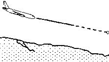
Mode 1
Excessive rate of descent with respect to the aircrafts height above the
ground. Two different warnings can be given. First, an advisory (sometimes
called a soft warning) of "SINKRATE", repeated every 3 seconds, and
illumination of the amber GRND PROX light. This can be inhibited by pushing the
GND PROX switch. Second, an aural warning (sometimes called a hard warning) of
"PULL UP", together with illumination of the "Pull Up" light.Both alerts
stop when the aircraft exits the respective warning envelopes (ie: reducing rate
of descent to one outside of the warning envelopes).
Mode 1 Excessive descent rate
Mode 2
This supplies warning protection when the terrain is rising
dangerously fast. These warnings are given well ahead of the aircrafts projected
collision with terrain. A gain in barometric altitude is required to stop the
alert. Mode 2 is in fact split into two separate sub-modes, mode 2a being if the
flaps are NOT in the landing position, and mode 2b if they are in the landing
position.
Mode 2a has an advisory aural of "Terrain,
Terrain", coupled with the illumination of the GND PROX G/S INHB switch
light. This can be inhibited by pushing the GND PROX G/S INHB switch.
If the aircraft radio altitude, speed and rate of closure
with the ground are within the warning envelope, an
aural message of "Pull Up, Pull Up", preceded by a
whooping sound will be heard. This warning can NOT be inhibited.
Mode 2b provides monitoring when the flaps are in the
landing position. Entering the envelope with the landing gear extended would
cause the repeated message of "Terrain, Terrain", coupled with the
illumination of the amber GND PROX G/S INHB switch light. Can be inhibited by
pushing the GND PROX G/S INHB switch.
Excessive rate of closure with terrain
Mode 3
This mode warns pilots of an excessive
altitude loss after takeoff or go
-around. Mode 3 monitors the
amount of radio altitude gained. If the barometric altitude lost equates to
approximately 10 % of the radio altitude gained, the "Don’t Sink" aural
warning will sound, coupled with an illumination of the amber GND PROX G/S INHB
switch light.
A second aural advisory of "Too Low Terrain" will
occur if the original radio altitude is greater than 150 ft AGL, and the radio
altitude then decreases by more than 25% of that radio altitude. As with a
"Don’t Sink" aural, the amber GND PROX G/S INHB switch light will illuminate.
Altitude loss after takeoff or go-around
Mode 4
This is divided into two submodes, mode 4a, and mode 4b. Both identify to
insufficient terrain clearance
during the climbout, cruise, descent and approach phases of
flight. This protection is especially valuable when the aircrafts flight path is
too shallow to develop excessive closure rates with terrain (Mode 2), or
excessive descent rates (Mode 1).
Mode 4 has three different alerts, depending on the phase of
flight and configuration of the aircraft.
A caution when the aircraft is near to the ground, and the
landing gear is NOT down, or the flaps are NOT in the landing position. Aurals
will be either "Too Low Gear", "Too Low Flap", or "Too low Terrain",
dependant on aircraft speed. The voiced warning will be repeated until the
flight condition is corrected. Once the landing gear and flap are set to the
landing position, the aurals will cease.
Unsafe
terrain clearance with landing gear/flaps not in landing position
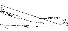
Mode 5
This concerns itself with an excessive deviation below
the glideslope whilst engaged in an ILS approach. It will be be active whenever
the runway being approached is equipped with an instrument landing system, and
the aircrafts navigation radio is tuned to the correct ILS frequency. In other
words, mode 5 is not going to provide a caution if your navigation radio is
tuned to a VOR, whilst engaged in a VOR approach.
This aural warning will warn the flight crew if the aircraft
descends to a position 1.3 dots or more below the ILS glideslope. As mentioned,
mode 5 has two volumes, soft and loud. The repetition rate is increased as the deviation from the glideslope increases, and radio altitude
decreases. The aural warnings are coupled with anillumination of the amber GND PROX G/S INHB switch light.This mode is only armed when a valid ILS signal is being
received, the radio altitude is 1, 000 ft or less, andthe landing gear is down.
The envelopes have two aural warning volumes, both of which are
"Glideslope".
This aural warning will warn the flight crew if the aircraft
descends to a position 1.3 dots or more below the ILS glideslope. As mentioned,
mode 5 has two volumes, soft and loud. The repetition rate is increased as the
deviation from the glideslope increases, and radio altitude decreases. The aural
warnings are coupled with an illumination of the amber GND PROX G/S INHB switch
light.
Below ILS glideslope
Windshear mode
The GPWS provides aural and visual warnings of significant
windshear conditions. The aural warning consists of a two tone siren, plus the
words "Windshear, Windshear, Windshear". The aural warning is given once
only during a windshear encounter, and is associated with the illumination of
the master warning "Windshear" light. Some EFIS equipped aircraft have a feature
which gives pitch and wing levelling guidance to pilots through the flight
director bars on the ADI.