
primary
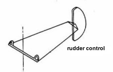
flight controls
These consist of the flight control surfaces and
the engine power management (unless you are flying
a glider that is!).
control
activation
In light
aircraft the control surfaces mentioned
above are moved by the power of the pilot's
muscles. Each control surface is connected
directly to the control column or rudder
pedals with a series of cables and pulleys
or rods.
In such a control system the control column
can move the control surface, but the
control surface can also move the column.
This is called a reversible control.
In large aircraft the pilot requires
assistance in moving the controls.
Assistance may be provided by electrical
motors or hydraulic jacks. When such a
system is employed the controls become
irreversible.
simple controls
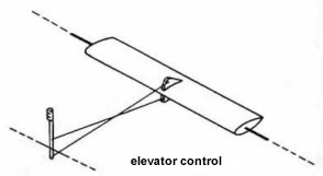 
A simple basic control system
as operated by a pilot
A
simple mechanical cable operated system as you will find on aircraft such
as the Cessna C152. The cables in some aircraft are replaced by rods.
The control column can be moved by raising and lowering the elevator

boosted control system
This is a simplified boost
system. When the pilot moves the column, tension in the cable or rod also
opens a valve letting pressure from a hydraulic or pneumatic pump expand a
slave cylinder that assists moving the control. The control column can be moved by raising and lowering the elevator
but a considerably more force is required.
fly-by-wire system
There is no mechanical
connection between the control column and the flight surface in a
'fly-by-wire' system. There is a sensor on the control column which
transmits the column's position to an actuator. The actuator then moves
the control surface to a position which matches the column's deflection.
This system is not reversible. (The control column will not be moved by
moving the control surface). The system is much lighter than the boosted
system and is used on all large aircraft nowadays.

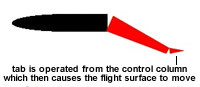
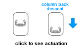
Tab Control
Systems
In the early
days of large aircraft many designers
avoided the need to provide boosted
controls, as described above, by using tab
activated controls. The DC-9 for example
uses tab actuated controls. In a tab
controlled system the pilot moves only a
small actuating tab on the larger control
surface. The force generated by the tab then
moves the main control. This is of course
the same way trim tabs work. Therefore, you
can think of this system as being like trim
tabs if they were connected to the control
wheel instead of a separate control wheel.
Note that in a tab controlled system there
is no direct connection between the control
column and the control surface.
servo and anti-servo tabs
Another way of changing the amount of force the pilot
must apply to the control column is through servo and anti-servo
tabs. In this system the control column is directly
connected to the control surface (just like a C-172) but a tab is
geared to the movement of the control surface so that it either
assists the movement of the control, or counters the movement of the
control. Thus, the controls can be made to feel heavier or lighter
than they would otherwise.
|
servo tab
|
anti servo tab

|
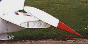
Control Horns
On an aircraft with
reversible controls
the pilot must apply
a force to the
control column
sufficient to keep
the the control
surface deflected in
the air stream. To
assist the pilot the
aircraft design will
usually provide a
control horn, such
as the one shown to
the right. The horn
is simply an
extension to the
control surface
which projects ahead
of the hinge. The
air striking the
horn assists the
pilot to deflect the
control surface.
Horns are usually
provided on
elevators and
rudders. Ailerons
usually do not
require horns.
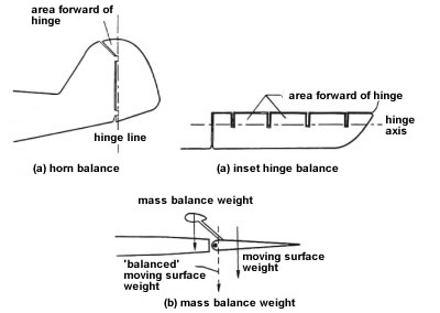
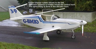
Mass Balance
When a control is
deflected a low
pressure area forms
on the cambered
side. This tends to
pull the control
back into alignment
with the wing,
stabilizer or fin as
the case may be.
However, the control
surface has mass and
therefore momentum.
If the centre of
gravity of the
control surface is
behind the hinge,
the control tends to
overshoot the point
of alignment. The
result is a tendency
for the control to
flutter. Flutter
could become
sufficiently severe
that the aircraft
could break up in
flight.
To solve the above
problem the control
must be balanced, so
that its centre of
gravity is in line
with the hinge.
click here
to see flutter movie
The exact distribution of weight on a
control surface is very important. For this reason, when a control surface
is repainted, repaired or component parts replaced, it is essential to
check for proper balance and have it rebalanced if necessary. To do this,
the control surface is removed, placed in a jig and the position of the
centre of gravity checked against the manufacturer's specifications.
Without any airflow over the control surface, it must balance about its
specified C.G. This is known as static balance. For example, the
aileron of the Bonanza is designed for a static nose heavy balance of 0.2
inch pounds. The C.G. of the aileron is forward of the hinge centreline
causing the control surface to be nose heavy.
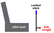
Bob
weights
Bob
weights
are
sometimes
known as
counter
weights.
Their
purpose
is to
change
the
amount
of
control
force
required
to
deflect
the
control
column
under
different
g-loadings.
Normally
the
amount
of force
the
pilot
must
apply to
the
control
column,
assuming
reversible
controls,
varies
with
airspeed
only.
However,
by
installing
a bob
weight
the
aeronautical
engineer
can make
it more
difficult
to pull
on the
control
column
as
g-force
increases. The
purpose
of the
bob
weight
is to
reduce
the
likely
hood the
pilot
will
overstress
the
aircraft.
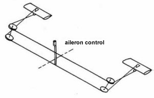
Differential
Ailerons
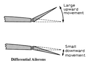
Differential
ailerons
are
designed
so that
the
up-going
aileron
rises a
greater
angle
than the
down
going
aileron.
When we
use
ailerons
we want
the ship
to roll
only on
its
longitudinal
axis.
The
problem
is that
to raise
a wing
the
aileron
increases
lift on
that
wing
with the
resultant
increase
in drag.
At the
same
time
there
usually
is a
decreased
lift on
the
opposite
wing
with a
decrease
in drag.
The
descending
wing has
less
drag and
moves
forward
while
the
rising
wing has
more
drag and
moves
backwards.
This
produces
a
tendency
to yaw
(turn)
in the
wrong
direction
or into
the
rising
wing and
away
from the
intended
turn
direction.
This
usually
results
in a
nose
high
slip
with the
fuselage
side
presented
to the
relative
wind
with
high
drag.
This is
called
"adverse
yaw" and
is fine
if you
need to
lose
altitude
with
lateral
fuselage
drag as
in a
landing
approach,
but bad
for
beginning
a
coordinated
turn
with the
fuselage
parallel
to the
relative
wind.
To
compensate
for this
problem
and make
flying
easier,
aircraft
are
usually
designed
with one
or a
combination
of a
number
of
methods
to
decrease
adverse
yaw.
The
common
fix for
adverse
yaw is
to
mechanically
produce
differential
aileron
movement
so that
there is
more up
travel
than
down. In
other
planes
the
aileron
is
hinged
towards
the top
of the
wing/aileron
joint so
that a
portion
of the
leading
edge of
the
aileron
sticks
down
into the
slipstream
creating
drag
when the
wing is
descending
to
balance
the
resultant
drag
from the
rising
wing.
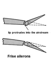
Frieze
Ailerons
Frieze
ailerons
are
designed
so that
when the
aileron
is
deflected
upward a
lip
extend
down
into the
air
stream.
As a
result
the
up-going
aileron
produces
more
drag
than the
down
going
aileron.
This
helps
provide
some of
the
force
required
to start
the
aircraft
yawing
in the
desired
direction
of the
turn.
Usually
this is
enough
force to
provide
the
required
turn
moment
but not
enough
to
overcome
aileron
drag.
Therefore,
the
pilot
will
still
need to
use the
rudder
to
coordinate
the turn
when
large
aileron
deflections
are
employed.
engine management
On
simple
aircraft
on which
student
pilots
usually
begin,
there
are two
controls.
The
throttle,
which is
always
black in
colour,
and the
fuel
mixture
control,
which is
always
red. Vernier
'push
pull'
controls
such as
in the
illustration
below
appear
to be
popular
with
Cessna.
More
power is
applied
if the
vernier
is
pushed
in.
Fuel is
shut off
to the
engine
if the
mixture
control
is
pulled
out. As
simple
aircraft
have
fixed
pitch
propellers,
increase
in
throttle
will
increase
the
RPM
of the
propeller.
For more
information
about
propellers,
see the
propeller
section.
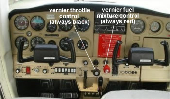
typical
Cessna
152
engine
management
controls
Other
aircraft
are
fitted
with
quadrant
lever
controls,
(Piper
for
example).
Power is
applied
by
pushing
the
lever
FORWARD.
The fuel
supple
to the
engine
is cut
off by
pulling
the
lever
back.
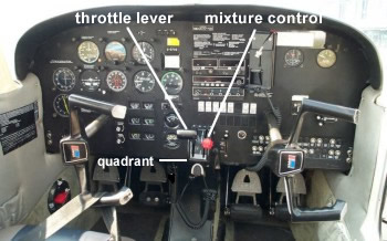
typical
quadrant
engine
management
controls
mixture
This is operated by the red
control. At close to sea level altitudes,
the mixture shown be maintained in the fully rich
position. This should always also be the case when
power setting are used that are more than 75%
available, the the fuel contributes to the cooling
of the engine. Once cruising altitude is reached,
the mixture can be leaned. This results in
considerable fuel savings. As the mixture is leaned,
the exhaust gas temperature increases. The gauge is
marked with a red line, and leaning should never
exceed this. If an exhaust gas temperature gauge is
not fitted the mixture can be adjusted by
observation. As the mixture is leaned, there will be
a small increase in engine RPM, or power in the case
of a complex aircraft. Continued leaning will result
in a decrease in RPM. The mixture should then be
enriched until it is just on the rich side of
maximum RPM.
At airfields of high altitude,
the mixture must be leaned to produce full power on
the ground, prior to take-off.
carburettor heat
While carburettor heat is not a
primary instrument, it is useful to include it in
this chapter. Incredibly many aircraft engines
are still fitted with carburettors, despite the fact
that fuel injection has been generally available
since half way through the last century. These
archaic devices have a nasty habit of freezing up
and preventing the fuel mixture from entering the
engine, which begins to run a tad rough and then
stops, sometimes with fatal results. This will
happen when operating close to the dew point, and
also when the engine is running under reduced power,
such as during a descent. It is up to the pilot to
periodically operate the carburettor (carb) heat control, which
is usually to the right of the throttle and mixture
controls. Carb heat control diverts hot air into the
carburettor from a sleeve around the exhaust system
and which will melt the offending ice. The engine
must ingest the resulting water, so sometimes it
will run rougher than before for a short period.
Carburettors can suffer from a variety of different
icing and this will be looked at later (see aircraft
technical 'induction system').
The carb. heat should always be applied during
descent.
The power to the engine is reduced when carb heat is
applied so it t is good practice to remove it just
before touchdown (say 100 feet) so that full power
is instantly available should a go around become
necessary.
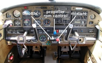
Complex
Aircraft
which
are
fitted
with a
constant
speed
propeller
have a
third
system
which
manages
the RPM
of the
propeller.
This is
always
blue in
colour.
The
throttle
in this
case
just
increases
available
power
and RPM
is
controlled
by the
propeller
control.
There is
an order
in which
these
controls
should
be used
to avoid
a
possible
overspeed
of
propeller.
increase
RPM
Blue
first
Black
second
decrease
RPM
Black
first
Blue
second.
Students
almost
always
begin
flying
in
simple
aircraft.
Further
training
is
required
to
operate
complex
types
such as
the
Piper
Arrow or
Mooney
series.
|
