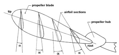
fig 6 - 4 cross section of a propeller. An a (alpha) denotes angle of attack of
airfoil sections
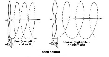
Propellers may be classified as to whether the blade
pitch is fixed or variable. The demands on the propeller differ
according to circumstances. For example, in takeoffs and climbs more power
is needed, and this can best be provided by low pitch. For speed at
cruising altitude, high pitch will do the best job. A fixed-pitch
propeller is a compromise.
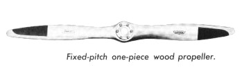
fixed
pitch propellers
The propeller is made in
one piece. Only one pitch setting is possible and is usually two blades
propeller and is often made of wood or metal.
Wooden Propellers:
Wooden
propellers were used almost exclusively on personal and business aircraft
prior to World War II .A wood propeller is not cut from a solid block but
is built up of a number of separate layers of carefully selected .any
types of wood have been used in making propellers, but the most
satisfactory are yellow birch, sugar maple, black cherry, and black
walnut. The use of lamination of wood will reduce the tendency for
propeller to warp. For standard one-piece wood propellers, from five to
nine separate wood laminations about 3/4 in. thick are used.
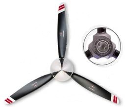
Metal Propellers:
During 1940, solid steel propellers were made for military use. Modern
propellers are fabricated from high-strength , heat-treated, aluminium
alloy by forging a single bar of aluminium alloy to the required shape.
Metal propellers is now extensively used in the construction of propellers
for all type of aircraft. The general appearance of the metal propeller is
similar to the wood propeller, except that the sections are generally
thinner.
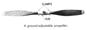
variable pitch propellers
There are two types of
variable-pitch propellers adjustable and controllable. The adjustable
propeller's pitch can be changed only by a mechanic to serve a particular
purpose-speed or power.
The variable pitch propeller
permits pilots to change pitch to more ideally fit their requirements at the
moment. In different aircraft, this is done by electrical or hydraulic means.
Two-position: A propeller
which can have its pitch changed from one position to one other angle by the
pilot while in flight.
Controllable pitch: The
pilot can change the pitch of the propeller in flight or while operating the
engine by mean of a pitch changing mechanism that may be operated by
hydraulically.
Constant speed
propellers
In modern aircraft, it is done
automatically, and the propellers are referred to as constant-speed
propellers. As power requirements vary, the pitch automatically changes,
keeping the engine and the propeller operating at a constant rpm. If the rpm
rate increases, as in a dive, a governor on the hydraulic system changes the
blade pitch to a higher angle. This acts as a brake on the crankshaft. If the
rpm rate decreases, as in a climb, the blade pitch is lowered and the crankshaft
rpm can increase. The constant-speed propeller thus ensures that the pitch is
always set at the most efficient angle so that the engine can run at a desired
constant rpm regardless of altitude or forward speed.
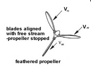
Constant-speed propellers may
have a full-feathering capability. Feathering means to turn the blade
approximately parallel with the line of flight, thus equalizing the pressure on
the face and back of the blade and stopping the propeller. Feathering is
necessary if for some reason the propeller is not being driven by the engine and
is wind-milling, a situation that can damage the engine and increase drag on the
aircraft.
Some controllable-pitch and
constant-speed propellers also are capable of being reversed. This is done by
rotating the blades to a negative or reverse pitch. Reversible propellers push
air forward, reducing the required landing distance as well as reducing wear on
tires and brakes.
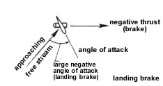
Beta Control: A propeller
which allows the manual repositioning of the propeller blade angle beyond the
normal low pitch stop. Used most often in taxiing, where thrust is manually
controlled by adjusting blade angle with the power lever.
Propeller theory
The forces.
Propeller blades are constructed using aerofoil sections to produce an
aerodynamic force, in a similar manner to a wing. Consequently the blades are
subject to the same aerodynamics – induced drag, parasite drag, wingtip
vortices, lift/drag ratios at varying aoa, pressure distribution changing with
aoa etc. There is a difference in application because, in flight, the propeller
has rotational velocity added to the translational [forward] velocity thus the
flight path of any blade section is a spiral – a helical flight path.
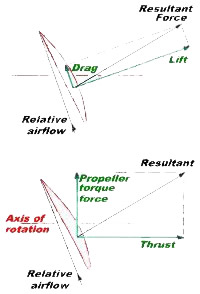
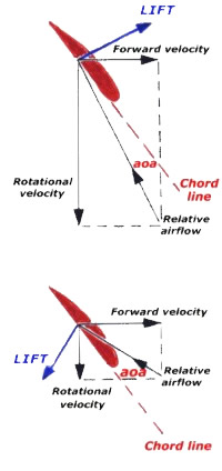
The diagram at left represents a blade section in flight and rotating around the
shaft axis. Because of the different application it doesn't serve much purpose
to express the resultant aerodynamic force as we would for a wing, with the
components acting perpendicular (lift) and parallel (drag) to that flight path,
as in the upper figure. So we represent the aerodynamic force component acting
forward and aligned with the aircraft's longitudinal axis as the thrust force,
and that component acting parallel to the direction of rotation as the propeller
torque force.
As you see in the lower figure the component of the lift acting in the
rotational plane has now been added to the drag to produce the 'propeller torque
force' vector. The remaining forward acting portion of lift is then the thrust.
That is why propeller efficiency is usually no greater than 80 – 85%, not all
the lift can be used as thrust and the propeller torque force consumes quite a
bit of the shaft horse power. The propeller torque and the engine torque will be
in balance when the engine is operating at constant rpm in flight.
There are other forces acting on the blades during flight, turning moments that
tend to twist the blades and centrifugal force for example. The air inflow at
the face of the propeller disc also affects propeller dynamics.
Blade angle and pitch
Although all parts of the
propeller, from the hub to the blade tips, have the same forward velocity, the
rotational velocity – and thus the helical path of any blade station – will
depend on its distance from the hub centre. Consequently, unless adjusted, the
angle of attack, will vary along the length of the blade. Propellers operate
most efficiently when the aoa at each blade station is consistent (and, for
propeller efficiency, that giving the best lift drag ratio) over most of the
blade, so a twist is built into the blades to achieve a more or less uniform aoa.
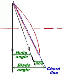
The blade angle is the
angle the chord line of the aerofoil makes with the propeller's rotational plane
and is expressed in degrees. Because of the twist the blade angle will vary
throughout its length so normally the standard blade angle is measured at the
blade station 75% of the distance from the hub centre to the blade tip. The
angle between the aerofoil chord line and the helical flight path (the relative
airflow) at the blade station is, of course, the angle of attack and the angle
between the helical flight path and the rotational plane is the angle of advance
or helix angle. The aoa and helix angle vary with rotational and forward
velocity.
The basic dimensions of propellers for light aircraft are usually stated in the
form of number of blades, diameter and pitch with the latter values given in
inches. e.g. 3 blade 64" × 38". The pitch referred to is the geometric pitch
which is calculated, for any blade station but usually the 75% radius position,
thus:
Geometric pitch = the circumference (2 π r) of the propeller disc at the
blade station multiplied by the tangent of the blade angle. Thus it is the
distance the propeller – and aircraft – would advance during one revolution of
the propeller if the blade section followed a path extrapolated along the blade
angle.
e.g. For a blade station 24 inches from the hub centre [0.75r] and a 14° blade
angle, the circumference = 2 × 3.14 × 24 = 150 inches and tangent 14° = 0.25.
Thus the geometric pitch is 150 × 0.25 = 38 inches. Propellers are usually
designed so that all blade stations have much the same geometric pitch.
Designers may establish the ideal pitch of a propeller which is the
theoretical advance per revolution which would cause the blade aerofoil to be at
the zero lift aoa; thus it would generate no thrust and, ignoring drag, is the
theoretical maximum achievable aircraft speed.
The velocity that the propeller imparts to the air flowing through its disc is
the slipstream and slip used to be described as the difference
between the velocity of the air behind the propeller ( i.e. accelerated by the
propeller) and that of the aircraft. Nowadays slip has several interpretations,
most being aerodynamically unsatisfactory, but you might consider it to be the
difference, expressed as a percentage, between the ideal pitch and the advance
per revolution when the the propeller is working at maximum efficiency in
conversion of engine power to thrust power. Slip in itself is not a measure of
propeller efficiency; as stated previously propeller efficiency is the ratio of
the thrust power (thrust × aircraft velocity) output to the engine power input.
Pitch and velocity
The performance of aircraft
fitted with fixed pitch or ground adjustable propellers is very much dependent
on the chosen blade angle. Fixed pitch propellers limit the rpm developed by the
engine at low forward velocity, such as occurs during the take-off ground roll
and may also allow the engine rpm to exceed red-line maximum when the load on
the engine is reduced, such as occurs in a shallow dive. Fixed pitch propellers
operate at best efficiency at one combination of shaft power and airspeed. Blade
angle is usually chosen to produce maximum performance at a particular flight
condition, for example:
• Vy climb i.e. a climb propeller
• Vc cruise i.e. a cruise propeller
• High speed.
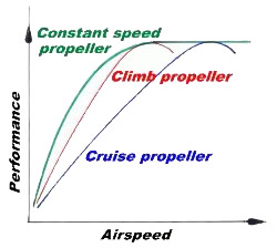
The climb propeller is usually
chosen when the aircraft normally operates from a restricted airfield or in high
density altitude conditions. The climb propeller will produce maximum efficiency
at full throttle around the best rate of climb airspeed and will perform fairly
well at take-off, but during the initial take-off acceleration even the climb
propeller may restrict the engine rpm to less than 75% power. The cruise
propeller will achieve maximum efficiency at 75% power at airspeeds around the
design cruising speed but aircraft take-off and climb performance will not be
the optimum. The cruise propeller usually has a little more pitch than the
standard propeller fitted to the aircraft. A high speed propeller might be
fitted when the aircraft is intended to be operating at, or above, rated power
for short periods – in speed competition for example.
A constant speed propeller allows the engine to
develop maximum rated power and rpm during the ground roll and to develop full
power throughout its normal rpm range. With a constant speed propeller the pilot
controls inlet manifold air pressure [MAP] with the throttle lever and
the engine rpm with the rpm control lever or knob/switches. The pilot has
several combinations of rpm/MAP to achieve a particular power setting. For
example, in one particular aircraft, the recommended combinations for 65% power
at sea level are 2100 rpm + 26 inches Hg MAP or 2200 + 25 inches or 2300 + 24
inches or 2400 + 23 inches. So you can use low rpm and high MAP or high rpm and
low MAP to achieve exactly the same power output. The low rpm / high MAP
combination probably gives more efficient cylinder charging and better
combustion plus less friction. The high MAP also acts as a cushion in the
cylinders, reducing engine stress. MAP is usually measured in inches of mercury
[Hg] rather than hectopascals. Standard sea level barometric pressure is 29.92
inches Hg or 1013.2 hPa.
The
windmilling propeller
The angle of attack of a fixed
pitch propeller, and thus its thrust, depends on the forward speed of the
aircraft and the rotational velocity. Following a non catastrophic engine
failure the pilot tends to lower the nose so that forward airspeed is maintained
while at the same time the rotational velocity of the engine/propeller is
winding down. As the forward velocity remains more or less unchanged while the
rotational velocity is decreasing the angle of attack must be continually
decreasing and at some particular rpm the angle of attack will become negative
to the point where the lift component becomes negative ([reverses) and the
propeller autorotates, driving the engine. This acts as greatly increased
aerodynamic drag which seriously affects the aircraft's L/D ratio and thus glide
angles. The drag (including the negative lift) is much greater than that of a
stationary propeller, also the engine rotation may cause additional mechanical
problems if oil supply is affected.
If the forward speed is increased windmilling will increase, if forward speed is
decreased windmilling will decrease, thus the windmilling might be stopped by
temporarily reducing airspeed, probably to near stall, so that the negative lift
is decreased to the point where internal engine friction will stop rotation.
This is not something which should be attempted without ample height.
In the diagram the upper figure shows the forces associated with a section of a
propeller blade operating normally. The lower figure shows the forces and the
negative angle of attack (aoa) associated with the propeller now windmilling at
the same forward velocity.
A variable pitch propeller may have a feathering facility which turns the
blades to the minimum drag position (i.e. the blades are more or less aligned
fore and aft) and halts windmilling when the engine is stopped.
The runaway
propeller
As a propeller system increases
in complexity then the possibilities for malfunction increase. A problem
associated with constant speed propellers is governor failure during flight
which, in most installations, will cause the propeller blades to default to a
fine pitch limit. This greatly reduces the load on the power plant, and the
engine will immediately overspeed, particularly if in a shallow dive. The rpm of
an overspeeding engine – sometimes referred to as a 'runaway prop' – will
quickly go way past red-line rpm and, unless immediate corrective action is
taken, the engine is likely to self destruct and/or the propeller blades depart
the hub due to the increased centrifugal force.
The corrective action is to immediately close the throttle and reduce to minimum
flight speed by pulling the nose up. . Once everything is settled down fly
slowly, consistent with the fine pitch setting, to a suitable airfield using
minimum throttle movements. (The constant speed propeller fitted to a
competition aerobatic aircraft usually defaults to the coarse pitch limit to
prevent overspeeding but an immediate landing is required.)
