takeoff and
climbAfter taxying to the holding
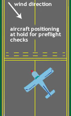
point of the runway in use, the aircraft is aligned to about 45° to the runway
and towards the wind. Aligning the aircraft in this manner ensure that the prop
wash created during the full power tests does not damage an aircraft that may be
behind you. The pre-takeoff check list is accomplished. The checks are always enumerated in the
pre-flight check list which should always be available in the cockpit. Checks
will include engine functions, and fuel. With the brakes full on, the engine is
run up to high revs, usually 2200 rpm, and each magneto is cut in turn. This
will result in an RPM drop which should normally not exceed 125 RPM. The carb
heat is tested, which should show a small drop in RPM. If the aircraft is
complex, the propeller is recycled twice by increasing pitch sufficiently to
reduce the RPM by at least 100. The engine RPMs are then dropped to tick-over to
ensure that even running is experienced. The fuel boost pump is switched on and
if the airfield is controlled, permission to line up is requested.
First degree of flap is usually
applied, and the elevator trim adjusted to neutral. When this is completed, and
clearance is given, the airplane is taxied to the
centre of the runway and aligned with it. The throttle is opened fully to
start the takeoff run (also called take off roll). During this takeoff run, the
control wheel, or stick, is usually held in the neutral position, but the rudder
pedals are used to keep the airplane on the runway's centreline. If the aircraft
has a castoring nosewheel, small dabs of differential brake will be required
until sufficient airspeed has been attained to give rudder authority.
The sudden increase in engine
power will place and uneven pressure on the empennage. This will result in a
tendency to yaw, which must be counteracted using the rudder pedals. Some
aircraft offset the engine installation to reduce the effect. Most engines
rotate clockwise, which will produce a yaw to the left and require right rudder.
Anticlockwise engines (some older British types for instance) will produce the
opposite effect. A large power decrease will cause the aircraft to yaw in the
opposite direction.
If a crosswind is present, the
control wheel is held towards the wind to prevent the windward wing lifting.
As takeoff airspeed is
approached, gentle back pressure on the control wheel raises the elevator which
causes the airplane's nose to pitch upward slightly. This lifts the nose wheel
off the runway
(see fig. below).
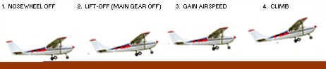
stages of a takeoff
Once the nose wheel is off the
runway, the more right rudder will probably have to be applied to counteract the left-turning tendency
which is greater once the aircraft leaves the ground. As the
airplane lifts clear of the runway, the pilot varies the pressure on the control
wheel. First, pressure is relaxed slightly to gain airspeed while still in
ground effect (additional lift provided by compression of air between the
airplane's wings and the ground). As airspeed increases to the best
rate-of-climb airspeed, back pressure on the control wheel is adjusted to
maintain that airspeed until the first desired altitude is reached. (Best
rate-of-climb airspeed provides the most altitude for a given unit of time.)
Once the runway is clear, the undercarriage is retracted (if the aircraft is
complex) and flaps are returned to neutral (clean) at about 300 feet.
Short
field take-off
In a short field take-off the
aim is to accelerate as fast as possible, be airborne well before the boundary,
to clear obstacles near the boundary while climbing at the maximum angle of
climb, and to maintain reasonable safety margins. Thus we are not so concerned
with protecting the undercarriage.
The procedure is to maintain a more or less level minimum drag attitude i.e. 4
or 5° aoa (with a nose wheel held just above the bumps) throughout the ground
roll until Vx is reached; then rotate directly to a 12° aoa and climb away at Vx
until obstacles are cleared; then reduce aoa to continue the climb at Vy or a
higher speed. The ground roll is longer but the acceleration is greater, because
rolling friction is normally less than induced drag at a low aoa: you reach Vx
in a shorter distance and the TODR is less. The aircraft is subject to all the
engine effects but an abnormal P-factor turning tendency should be anticipated
after the lift-off rotation.
As in normal take-off the procedure may vary a little if the aircraft is fitted
with flaps that can be set to a position which provides increased lift without a
significant increase in drag. The recommended flap setting for a short field
take-off may vary from that for other take-off conditions, as the flap position
that facilitates minimum ground roll may decrease climb performance. There are
some suggestions that flaps should not be lowered to the take-off position until
the aircraft is nearing lift-off speed (so that the initial acceleration is
faster) but the slight advantage provided by this can be dramatically offset by
inadvertently lowering the flaps past the take-off position. Better to set the
flaps when doing the pre-take-off checks where there is time to double check the
selected position.
There may be a suggestion that an aircraft equipped with brakes is run up to
full power at the start of take-off, while holding on the brakes; but generally
it is probably better to smoothly run up to full power whilst the aircraft is
rolling; there being less chance of stone damage to the propeller, and it is
easier to prevent a swing developing. Swings and swing correction reduce the
acceleration, and it is better to allow time at the beginning of the ground roll
to get the aircraft firmly under control.
Obviously a take-off into wind is highly desirable, unless runway slope and
rising terrain dictate otherwise, and the ground roll should be started as close
to the boundary fence as reasonably possible. The procedure described above is
for a hard, dry surface or for short, dry grass. If the surface is soft or the
grass is long and wet then the rolling friction may exceed the induced drag at
medium aoa or the slippery surface may make directional control difficult. In
such cases it may be better to get the wheels off early and fly in ground effect
until Vx is attained, as in the soft field technique. If there are any doubts
about the take-off conditions then stay on the ground.
Soft
field take-off
Soft field procedures may be
applicable to muddy, waterlogged or long/wet grass surfaces. The prime aim in a
soft field take-off is to reduce the extremely long ground roll, accepting to
become airborne with less than adequate initial airspeed safety margin while
utilising ground effect for fast acceleration. The following procedure should
not be used in turbulent or gusty conditions, as the possibility of a stall
after lift-off is increased.
In very soft conditions the usual technique is always to keep rolling, i.e. do
not taxi to the take-off position and then stop to do the take-off checks, they
should be completed beforehand. When lined up open the throttle fully and
smoothly whilst holding the control column back. Use of a maximum lift flap
setting is usually highly recommended. As the elevators become effective the
nose of a nosewheel aircraft will rise; if a taildragger the elevator pressure
should be sufficiently relaxed so that the tail wheel is held off the surface
but the aircraft should remain firmly in a tail down attitude. As ground speed
builds start relaxing the back pressure and the aeroplane will lift itself [or
more likely lurch and stagger] from the surface at its minimum unstick speed [Vmu]
and at an aoa very close to the stalling aoa, so it is vulnerable to turbulence
and mishandling. Also P-factor and slipstream effect may come into play at this
time and it is important to keep the wings level with aileron and stop any turn
with opposite rudder – to negate any cross-controlled skid.
The pilot must then smoothly reduce aoa to 5° or 6° and hold the aircraft just
above the surface, in ground effect, so that it accelerates at the maximum
possible rate. Gyroscopic effect may be significant during the pitch down to the
smaller aoa, which must be anticipated with rudder. The aircraft is rotated
after Vy (or Vx if there are obstructions) is attained to break it out of
ground effect, held for a few moments to ensure it will accelerate, and then
climb-out is commenced. At the initial rotation the aircraft will slow as
induced drag increases substantially and rapidly, firstly, because of the
restoration of the normal induced drag as it pulls out of ground effect, and
secondly because of the increased aoa. The aircraft is likely to sink back to
the surface if rotation occurs before sufficient speed is built.
The TODR for a soft field take-off will be considerably longer than that for a
normal take-off. It is most unwise to attempt take-off from an airfield that is
both short and soft.
Coping with significant crosswind
During the initial stages of the
ground roll in any type of take-off with a significant crosswind component the
aircraft will tend to weathercock into wind, pivoting around the main wheels.
There are lateral stresses on all wheels in contact with the ground during the
roll. The lateral control of the aircraft is then very much dependent on
adequate tyre contact with the surface, so if the surface is slippery a
crosswind take-off may not be advisable. As the aircraft accelerates the
relative wind velocity (combining the ambient wind velocity, the aircraft's own
forward speed and the slipstream velocity) over the tailplane surfaces, will
have an increasing headwind component and a (relatively) decreasing crosswind
component. Thus it is normal to start the ground roll with a large rudder
deflection to counter weathercocking, with the deflection decreasing as speed
builds.
It is usually advisable to also raise the into-wind aileron to prevent the
into-wind wing from rising, particularly if gust induced; the inclined lift
vector because of the rising wing will tend to turn the aircraft away from the
wind. Be aware that if the into-wind aileron is raised, whilst you are
countering the weathercocking with rudder, then you must be operating
cross-controlled, which will cause the aircraft to sideslip into wind if you
should get airborne in that condition.
The aileron deflection is decreased as speed builds, but in strong crosswinds it
may be advisable to actually lower the into-wind wing so that the aircraft is
rolling just on the into-wind main wheel. The lift vector is then inclined from
the vertical and has a lateral component which counteracts the effect of the
crosswind, the aircraft line of roll being kept straight by the friction of that
into-wind wheel. If the angle is correctly judged there should be no stress on
the wheel. As the aircraft is being lifted off the ailerons should be returned
to neutral and the wings levelled.
To provide an additional safety margin the aircraft should be held on the ground
for a higher than normal lift-off speed, plus if conditions are gusty, add 50%
of the wind gust speed in excess of the mean wind speed e.g. wind speed 10 knots
gusting to 20 knots, add 5 knots to the lift-off airspeed. If the aircraft does
become prematurely airborne for any reason then, rather than let the wheels bump
down again, hold the aircraft off the ground, accelerate in ground effect and
use the soft field take-off technique.
After becoming airborne the aircraft will drift away from the heading, so to
mark a tidy and controlled departure, the aircraft must be gently turned, onto a
new heading that will compensate for the drift and the 'track made good' will
follow the extended line of the ground roll, at least until the aircraft reaches
500 feet agl; at which height regulations allow a turn in the circuit direction.
It can be that the crosswind either amplifies or reduces the slipstream and
other effects. It may be wise to consider taking off in a direction that takes
advantage of that counter effect even if that entails taking off with a tailwind
component. Also there is no rule that says you must always take-off aligned with
the centre of the runway or strip, if crosswind conditions warrant it plan your
ground roll at an angle across the strip – edge to edge.
Causes of take-off
accidents
One or more of the following factors are
commonly causal in take-off accidents:
• exceeding weight and balance limitations
• failure to set elevator trim at the correct position for the airframe
configuration
• over-controlling during the ground run and at lift-off
• premature lift-off
• climbing too steeply after lift-off
• failure to calculate the TODR and particularly the effects of high
density altitude
• failure to abandon take-off early enough when it is apparent that
airfield surface conditions preclude a safe departure
• using an excessive bank angle in a climbing turn.
Engine failure after
take-off [EFATO]
Pilots should always be prepared for the
possibility that the engine will lose partial or total power during the
take-off and climb out; or, for that matter, at any other time during
flight. When such an event occurs the cardinal rule is to fly the
aeroplane, which initially implies quickly getting the nose down into the
right attitude for an appropriate airspeed, either Vbg or Vmd depending on circumstances. Some
say the second and third edicts should also be 'fly the aeroplane' and
'fly the aeroplane'. ( However if a partial power loss is accompanied
by extreme vibration or massive shaking of the aircraft then it is just as
important to get the engine completely shut down.) |
Precautions when taking off towards rising terrain
Take-offs should always be
planned so that they do not cause nuisance to others but it is also prudent to
avoid taking off in a direction that takes you close to structures, trees, masts
and powerlines unless you are sure that the aircraft will clear them by whatever
safety margin you consider acceptable within the existing atmospheric
conditions.
A take-off toward rising terrain is not something that should be undertaken
without a thorough check of all conditions, even if such a take-off has
previously being undertaken at a particular location without incident. Density
altitude, wind and other conditions may be such that another take-off will
result in a 'controlled flight into terrain' incident.
Ascertaining terrain height
The height of the terrain above
the airfield – or more particularly the angle of climb needed to safely clear it
– has to be ascertained, by whatever means available, to confirm that the
aircraft's rate of climb will more than outmatch both the increasing terrain
height and the effect of air downflow from the slope.
A simple way to judge the angle of climb needed is to extend your arm fully
with the fingers bent so that your extended line of sight, including the bottom
edge of your little finger, is horizontal. The width of each finger is around 2°
and the width of the palm is around 10°.
For an example we will have a look at 'farmer Jones's' airstrip on that
hot summer afternoon. Here there is but one grass strip, 1000 feet in length and
oriented north/south. Northward, and starting near the end of the strip, the
terrain has a 1 in 10 slope rising toward an extensive crescent ridge with an
elevation 1000 feet above the airstrip. Using the 1-in-60 rule we can calculate
that a 1 in 10 slope equates with an angle of slope of 6°.
Ascertaining angle of climb
needed
We established our aircraft's
practical rate of climb at sea level in standard ISA conditions as 850 feet per
minute and Vy = 65 knots or 6500 feet per minute. (One knot is near enough to
100 ft/min so to convert knots into feet per minute just multiply by 100).
Then using the 1-in-60 rule we can estimate our aircraft's sea level angle of
climb in nil wind conditions, thus:- 850/6500 × 60 = 8°. Also note that the
ratio of vertical speed to forward speed is about 1:8.
But we are not operating in sea level ISA conditions and Vy is only an indicated
airspeed not a true airspeed. TAS is close to 1.5% greater than IAS for each
1000 feet of density altitude, so at our density altitude of 5280 feet TAS is
(1.5 × 5.28) % = 8% greater = 65 × 1.08 = 70 knots or 7000 ft/min. Also our
practical rate of climb will be reduced by 10% per 1000 feet density altitude (=
52.8%) to 400 ft/min and the ratio of vertical speed to forward speed has been
reduced to 1:18.
Using the 1-in-60 rule the angle of climb in nil wind conditions, is then:-
400/7000 × 60 = 3.4°. Comparing the climb slope with the terrain slope of 6° we
can see that it is impossible to outclimb the terrain, in fact the impact point
will not be very far from the end of the strip.
But what would be the climb angle if we chose to climb at
Vx, which
should provide a ratio of vertical speed to forward speed 10% -15% better than
Vy. If Vx then provided a ratio of 1:15.5 the climb angle, using 1-in-60, would
be nearly 4°, which would extend the impact point a little further up the slope.
Effect of
wind on angle of climb
A reasonably steady horizontal
headwind makes some difference to the angle of climb. Let's say that headwind is
15 knots which would have the effect of reducing the aircraft's Vy ground speed
by 1500 ft/min to 5600 ft/min, so the angle of climb would be 400/5600 × 60 =
4.3°. However winds that cross over slopes are not horizontal, they may have a
substantial vertical component so the gain because of the reduction in forward
ground speed may be more than offset by a reduction in vertical speed, in fact
the downflow rate of sink can easily exceed the aircraft's rate of climb, in
which case a "controlled flight into terrain" is inevitable.
Limiting
climbing turns during take-off
The accelerated stall happens
when the airspeed at which an aircraft will stall depends on the wing loading
and, as a consequence of providing the centripetal force for the turn, wing
loading increases as angle of bank increases. For instance, the wing loading
increases slowly up to a bank angle of 30° – where it is 15% greater than normal
– after which it increases rather rapidly, being 41% greater at a 45° bank
angle. Bank angles exceeding 20 – 25° should not be made at low levels –
including take-off and landing operations.
The wing loading increase in the turn is provided by an increase in
CL
which in itself is brought about by an increase in aoa. We also know that the
lift coefficient increases in direct relationship to increase in angle of
attack. Now what will happen if we are climbing at Vx and decide to quickly turn
away from rising terrain or an approaching aircraft, using a 45° bank angle,
while still climbing? We know from the table that to maintain a 45° level or
climbing turn, wing loading and thus aoa, must increase by 41% and that the aoa
at Vx is probably around 12°, so that a 41% increase will take the aoa to 17°
and the aircraft will stall.
Full power stalls in a balanced climbing turn tend to result in the outer wing
stalling first, because of the higher aoa of the outer wing, with a fairly fast
wing and nose drop (particularly so if the propeller torque effect is such
that it reinforces the roll away from the original direction of turn and the
aircraft is a high wing configuration) and likely to result in a stall/spin
situation that any pilot lacking spin recovery experience may find difficult to
deal with. If the climbing turn is being made with excessive bottom rudder then
the lower wing might stall first with the consequent roll into the turn flicking
the aircraft over. Recovery from a stall in a climbing turn is much the same as
any other stall – ease the control column forward to about the neutral position,
stop any yaw, level the wings and keep the power on.
Even a 30° banked climbing turn at Vx will produce an aoa of 14°, very close to
the stall aoa and providing no margin for even minor turbulence or slight
mishandling. The margin which you should always have in hand, to cope with such
events, is 3 or 4°, which indicates that, when climbing at Vx, turns should not
be contemplated. Even when climbing at the Vy aoa [ around 8° ], until a safe
height has been gained, turns should be limited to about 20° to allow an
additional margin should wind shear be encountered in the climb out – and the
nose lowered a little for the turn.
Factors
affecting safe take-off performance
Apart from the pilot's condition
and capability, take-off performance is limited by the following constraints,
all of which should be carefully assessed within pre-take-off procedure to
establish whether a safe take-off is viable.
-
Aircraft weight and balance.
The critical nature of aircraft weight and balance at take-off should be
considered.
-
Standard take-off distance.
TOD should always be expressed as the total distance required to accelerate
from a standing start and clear an imaginary screen which is 50 feet, or 15.2
metres, high. The ground roll is that first part of the TOD where the
aircraft's weight is supported, or partly supported, by the undercarriage;
sometimes people incorrectly refer to the ground roll as the TOD, ignoring the
fact that the distance covered from the lift-off point to clear 50 feet may be
longer than the ground roll. It is not unknown for an under-powered aircraft
to be able to lift off but then be unable to climb out of ground effect; as
discussed below.
TOD is officially expressed as the take-off distance required [TODR] to
clear the 50 feet screen. Note that these standards require that the operating
conditions associated with a particular TODR will be specified in approved
aircraft take-off performance charts. These conditions are pressure altitude,
temperature, runway slope and surface, and wind velocity.
'Short, dry grass' is taken to mean grass less than 100 mm long.
Unless the manufacturer's take-off performance figures are published as an
approved performance chart within the aircraft's Flight Manual, or
comparable document, then such figures should be treated as unverified sales
claims. In the absence of any specified conditions in an unapproved
performance chart, assume that sea level ISA, nil wind and smooth, dry runway
are the basis for the published data.
-
Stopping distance required.
The distance required to reach flight speed and then bring the aircraft a
halt, should be known. It may be necessary to abandon the take-off soon after
lift-off, due to doubtful engine performance or other event – this is
particularly important in short field or 'hot and high' take-offs. If take-off
and landing distance [over a 50 feet screen] charts are available then the
total distance needed to take-off, abandon take-off at 50 feet, land and bring
the aircraft to a halt is just the sum of the charted take-off and landing
distances required.
-
Airframe condition.
An airframe in a battered or dirty condition, or which sports unnecessary or
non-standard accoutrements, will increase drag and retard acceleration,
lengthen TODR and reduce climb performance.
-
Engine age, condition and
operating temperatures. An engine
which is incapable of producing its designed rpm and torque will reduce
acceleration, lengthen TODR and reduce climb performance. The engine
manufacturer's instructions regarding warm-up procedures should be followed,
to ensure appropriate temperatures and pressures are established, before the
engine is subject to the stresses of take-off power; otherwise the potential
for an 'engine failure after take-off' is greatly increased.
-
Propeller condition and
pitch. Chipped leading edges or scored
blades, apart from being dangerous due to the possibility of delamination or
fracture, will adversely affect thrust output. Blade pitch at a coarse
setting, a 'cruise' setting, will reduce acceleration and climb performance.
-
Tyre pressure.
Under-inflated tyres increase the rolling friction, decrease the acceleration
and will add maybe10% to the ground roll.
-
Airfield dimensions and
slope. The usable length of runways or
strips must be known, as well as the degree of slope. Taking-off upslope will
reduce acceleration and lengthen the ground roll as thrust must also overcome
a force equal to the aircraft weight × the sine of the angle of slope, in
addition to drag and rolling friction. The ground roll will increase by about
15% for each 2% of upslope. Runway slope can be measured by taking an
altimeter reading at each end, divide the elevation difference by the runway
length (in feet) and multiply by 100 to get the approximate slope percentage.
-
Airfield surface and
surrounds. A short dry grass or rough
gravel surface might add 10% to the ground roll compared to that for a smooth
sealed surface. Wet or long grass might add 50% to the ground roll and a soft
or waterlogged surface might double the ground roll. Surface water and/or wet
grass can lead to aquaplaning and loss of directional control. The height of
obstructions and local terrain must be known.
-
Airfield density altitude.
A critical factor which is often not correctly assessed, the density altitude
has a major effect on engine output, propeller performance and lift generated.
Thus it affects acceleration, TODR and climb performance to such an extent
that on 'hot and high' airstrips an aircraft may be incapable of safe
take-off and climb-out.
-
Wind velocity and
turbulence. After weight and balance
and density altitude; wind strength, direction, gradient, downflow, gust
intensity, surface turbulence and the potential for wind shear events are
normally the major considerations in take-off performance for a properly
maintained aircraft.
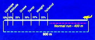
At left an indication of
possible cumulative effect of some take-off conditions on TODR; but as explained
below the take-off distance required can be much greater.
The pilot in command of an aircraft must assess all the foregoing factors and
conditions to ascertain the cumulative total distance required for take-off and
obstacle clearance and then judge if the take-off can be safely conducted. The
golden rule is "If there are any doubts, don't fly".
The most favourable conditions for optimum take-off performance at MTOW are:
- a pilot who follows the rules and the
recommended procedures
- an aircraft in very good condition and fitted
with a 'climb' or variable pitch propeller
- a surface that is dry, smooth and level – or
with a slight downslope
- a low density altitude i.e. low elevation and
low temperature
- a smooth full headwind of reasonable and
constant velocity.
You should not only be concerned that the
take-off is conducted safely, it should also be accurately controlled, beginning
with taxiing, so that alignments, headings, attitude and airspeeds – the
'numbers' – are properly maintained throughout. The take-off should take
advantage of the aircraft's and engine's maximum rate of climb capability to
reach the threshold height – and it should look well executed to an informed
observer standing behind the aeroplane's take-off point. In addition you must
have pre-established plans to safely cope with partial or total power loss,
occurring at any stage of the take-off sequence.
Engine
effects and aerodynamic phenomena
There are some engine effects,
plus aerodynamic and inertia phenomena, which will be noticeable at take-off,
but both their existence and the extent of their effect are dependent on the
configuration of the aeroplane. Tailwheel aeroplanes are particularly subject to
these phenomena, which can cause difficulties to any pilot who is inexperienced
in the slow speed handling of such aeroplanes.
The lower the power loading, or the higher the power-weight ratio, the
greater, and faster, the reaction will be to the engine effects.
The helical
slipstream
The propeller blades produce a
rotating slipstream tube with a diameter equal to that of the propeller disc and
a helicity that increases as forward speed increases. If the propeller rotates
clockwise, when viewed from behind the aircraft, the slipstream tube will also
rotate clockwise. Now imagine that the engine is mounted in the nose, as with
the Jabiru, then the slipstream will be rotating clockwise around the fuselage
and anything mounted below the fuselage will experience increased pressure on
the right side, from the slipstream striking it at an angle, and anything
mounted above the fuselage will experience higher pressure on the left side. The
significant surfaces mounted above the fuselage are the fin and rudder and the
increased pressure on their left hand side will tend to push the tail to the
right i.e. in nil wind conditions the aircraft will want to swerve to the left;
particularly in the early stages of the take-off run when the slipstream counts
for practically all the airflow around the fin and rudder. The swing direction
would be reversed for aircraft with the propeller rotating anti-clockwise.
Full application of compensating rudder may be required at the start of the
ground roll, but the helical effect lessens as the aircraft accelerates (because
the angle at which the slipstream meets the vertical surfaces lessens and also
the rudder becomes increasingly effective) so rudder pressure is decreased as
the take-off roll progresses. Slipstream effect is not so apparent in the
landing ground roll because normally the throttle is closed.
However if the engine is mounted above the fuselage the rotating slipstream tube
will be higher relative to the fin and rudder and the swing effect may be
lessened or reversed: aircraft with a pusher engine mounting are subject to the
same effect. Before you fly any aircraft it is advisable to determine which way
the aircraft will swing and how to control the swing.
The helical slipstream will also meet the horizontal stabiliser at an angle but
the resultant effect is difficult to determine or distinguish.
When a tailwheel aircraft has all wheels on the ground, as in the early part of
the take-off ground roll, the slipstream may be deflected by the airfield
surface so that the effect on the fin and rudder may vary between the tail-down
and tail-up positions.
Propeller
torque effect
The reaction torque of a
propeller rotating under power attempts to rotate the aircraft about the
propeller shaft; of course it is prevented by the resistance of the wings and
undercarriage, however, at the beginning of the take-off run the torque may be
sufficient to increase the friction on one tyre and thus cause the aircraft to
pull towards that side. The effect is there in the early stages of take-off but
may not be apparent as such, because it reinforces the swing tendency initiated
by the helical slipstream. (The propeller torque on some very high-powered
piston engine fighter aircraft has been such that at full power the aircraft
tended to hop sideways down the runway. In such aircraft the engine was not
opened up to full climb power until airborne.)
Gyroscopic precession effect
Any applied torque which tends
to alter the direction of the axis of a spinning gyroscope causes the direction
of the axis to move slowly [precess] 90° to the applied force and in the
direction of rotation. A fast rotating propeller disc acts as a gyroscope and
the precession effect may be noticeable as a slight vertical nose movement when
a level turn is initiated in flight, but it is particularly apparent when the
tail of a tailwheel aircraft is raised during take-off; when it may cause a fast
acting swing to the left – for a clockwise rotating propeller. The pilot must
anticipate this action by applying compensating rudder as the tail is lifted.
The same might apply when the tail is lowered during the landing run, with a
swing in the opposite direction, but it is unlikely as normally the engine would
be idling.
Gyroscopic precession effect is dependent on the rate of change in pitch or yaw,
the rotational speed and the moment of inertia of the propeller.
P-factor
P-factor, or asymmetric disc
effect or asymmetric blade effect, occurs when the thrust line is not
aligned with the flight path i.e. when flying with a high angle of attack. As
the propeller disc is then inclined to the relative airflow a down-going
propeller blade has a greater component of forward velocity than an up-going
blade, thus the down-going blade generates just slightly more thrust than the
up-going blade. For a clockwise rotation more thrust is then generated on the
right hand side of the disc which again reinforces the slipstream, torque and
gyroscopic induced tendencies for such aircraft to swing left during take-off.
However, P-factor is dependent on thrust and proportional to forward speed, so
it is not a significant factor in the initial part of the ground roll for a
tailwheel aircraft, even though the axis of the airscrew disc is inclined to the
horizontal; but it will become increasingly apparent as the ground roll
progresses if the aircraft's tail down attitude is maintained. P-factor may also
become apparent as higher velocities are reached – just before and after
lift-off, if a high aoa is employed at those stages. P-factor may cause the
aircraft to yaw when flying level with high power at high angles of attack.
P-factor has little or no effect on a tailwheel aircraft during the landing
ground roll because, normally, when the throttle is closed no thrust is
produced, only propeller drag. However should the throttle be suddenly opened
during the ground roll whilst the tail wheel is on the ground, anticipate a
prompt P-factor reaction.
Inertial effect of
centre of gravity position
If the aircraft's centre of
gravity is behind the main wheels, as it must be in a tailwheel undercarriage
aircraft, then any ground swerve – initiated by the helical slipstream,
gyroscopic effect, torque, a crosswind, wind gust, deflating tyre or rough
ground – will tend to be reinforced by the inertia of the aircraft, applied
through the cg position, tending to pivot around the main wheels. When the cg,
of the loaded aircraft, is in front of the main wheels, i.e. a nose wheel
undercarriage, the aircraft's inertia will lead to self-correction of the swing;
provided there is no excessive weight on the nose wheel. The cg inertial effect
is usually much more likely to cause real difficulties when a tailwheel aircraft
is slowing i.e. on landing, rather than when accelerating. Be aware that there
are circumstances where the cg inertial effect also applies to nosewheel
aircraft.
It is very important in such aircraft to identify any departure from the planned
heading at a very early stage i.e. within 2° or 3°, and take prompt corrective
action – but not to the extent of overcontrolling. The pilot must recognise the
swing, stop it, correct the heading and then halt the correction. Over
correction is exacerbated by a hard, smooth runway surface. A groundloop
is a swing that has been accentuated by the inertia effect into a very rapid
180° movement, often causing wing tip and undercarriage damage and tending to
occur at speeds between 5 and 25 knots. At low speeds and/or in light winds the
inertia effect is stronger than any weathercocking action.
There are occasions when it is necessary for a pilot to induce a groundloop,
usually when nearing the boundary fence at speed after a badly misjudged
landing. The groundloop is induced by applying full rudder together with full
brake on that side.
The swing effect is exacerbated if a tailwheel aeroplane is 'short-coupled' i.e.
the moment arm between the tail wheel and the main wheels (or the fin and the
cg) is short and thus the tail wheel friction moment is less than it might be.
Such aircraft swing very rapidly.
The inertia effect requires that taxiing techniques for tailwheel aeroplanes
differ to those for nosewheel aeroplanes. A turn initiated by rudder or brake in
a nosewheel aircraft will stop as soon as the pilot removes rudder or brake
pressure, because the inertia effect is always trying to straighten up the
ground path (wind conditions permitting). However with a tailwheel aircraft once
a turn is initiated the inertia effect will keep the turn going – and possibly
tightening – until the pilot takes definite action, by use of opposite rudder or
brake, to halt the turn.
Ground
effect
In the aerofoils and wings
module we saw that induced drag was a consequence of lift generation and the
associated wing-tip vortices increase the momentum imparted to the downwash.
When an aircraft is flying very close to the airfield surface, during take-off
and landing, the formation of the vortices is partly impeded by the proximity of
the ground and induced drag is less than normal.
The phenomenon is ground effect and implies faster acceleration on
take-off (which can be very useful) and slower deceleration on landing (which
generally is not useful) but it can only occur when the lower surfaces of the
wings are less than one full wingspan from the surface. The closer the airborne
aircraft is to the surface the greater the induced drag reduction. A light
aircraft with a wingspan of 10 metres, holding height with the wing
under-surface two metres above the ground, might experience a 30% – 40%
reduction which, at low speeds, would amount to a 15% – 20% reduction in total
drag.
It should be borne in mind that induced drag is normally a much greater force
than the wheel/tyre rolling friction on a smooth, dry surface. Also if flying in
ground effect utilising maximum available power and a disturbance causes the
aircraft to lift further away from the ground, the induced drag will be
immediately restored with a consequent decrease in airspeed, decrease in lift
and substantial sink towards the ground. Similarly if maintaining a constant low
velocity whilst in ground effect, i.e. neither accelerating or decelerating
[and which is poor energy management practice but can readily occur in an
underpowered or over-weight aircraft or when attempting take-off in high density
altitude conditions] it may be found that the aircraft will not break out of
the ground effect because, as the aircraft is pulled up, the induced drag
increases, velocity slows, lift decreases and the aircraft sinks back into
ground effect. If the aircraft is not able to be accelerated it may end up
tripping over the boundary fence, unless the throttle is closed and the aircraft
landed.
Calculating density altitude
Cold winter morning:
temperature is 0 °C and by setting 1013.2 on the altimeter pressure setting
scale we read off the pressure altitude as 1600 feet. [We remember, of course,
to then reset the scale to local or area QNH].
The temperature of 0 °C is 11 °C less than ISA so the density altitude variation
due to temperature variation is (minus)11 × 120 = minus 1320 feet.
So density altitude = pressure altitude ± temperature variation = 1600 – 1320 =
280 feet
Thus the aircraft should perform well at take-off, close to its rated sea level
capability.
Hot summer afternoon: temperature is 35 °C and by setting 1013.2 on the
altimeter pressure setting scale we read off the pressure altitude as 2400 feet.
The temperature of 35 °C is 24 °C greater than ISA so the density altitude
variation due to temperature variation is (plus) 24 × 120 = plus 2880 feet.
So density altitude = 2400 + 2880 = 5280 feet
Thus the aircraft will perform poorly at take-off, probably at less than 70% of
its rated sea level capability.
The following is an extract from an RAAus incident report:
"I was attempting to take-off in a paddock approximately 140 metres in
length. Due to the hot [35 °C] conditions the aircraft did not get enough lift
which resulted in the main wheels catching the top wire of the boundary fence.
The aircraft was slowed and struck the ground in a nose-down position. The wire
snapped allowing the aircraft to bounce approximately 20 feet in the air. I cut
the power and landed the aircraft to the left to miss another fence. This caused
the left wingtip to strike the ground before coming to a stop. I walked away
from the accident."
The aircraft manufacturer provided the following information:
"... the take-off distance to safely clear a 15
metre obstacle is 213 metres in ISA sea level conditions."
Rule of
Thumb #1
In the absence of manufacturer supplied data the effect of density
altitude on TODR (for a dry, smooth and level surface) can be roughly
estimated:-
"In nil wind conditions, for each 1000 feet that the pressure altitude
exceeds sea level add 10% to TODR, then for each 10 °C that the airfield
temperature exceeds 0 °C add a further 10%."
e.g. the 'Olly's Folly' hot day situation, the aircraft manufacturer's
standard sea level TODR is 250 metres.
Pressure altitude is 2400 feet: 250 × 1.24 = 310 metres.
Temperature is 35 °C: 310 × 1.35 = 419 metres TOD.
Then add a further 10% margin for random events = 460 metres estimated
TODR, but this is for a dry, smooth and level surface, if the surface is
long grass with a 2% upslope then you might have to add another 50% to
TODR making it nearly three times the manufacturer's standard distance!
Remember that all the factors
mentioned above relating to surface, slope, pressure, temperature,
airframe and engine condition are cumulative and the runway length is
finite. |
Rule of
Thumb #2
In the absence of manufacturer supplied data the effect of density
altitude on maximum rate of climb at Vy can be roughly estimated:-
Let's say our aircraft's manufacturer states the rate of climb at sea
level in standard ISA conditions is 1000 feet per minute at Vy. However
manufacturers' standard sea level rates of climb are usually based on an
aircraft in factory new condition, flown by a very accurate pilot in the
most benign atmospheric conditions. The manufacturer's standard should be
downgraded by a factor that represents an adjustment for general engine,
propeller, airframe and other conditions – say 15%, thus the practical
rate of climb at sea level in standard ISA conditions should be
regarded as 850 feet per minute at Vy.
"The practical rate of climb at Vy should be reduced by 10% for each
1000 feet of density altitude."
e.g. At a density altitude of 5000 feet a 50% reduction to 425 ft/min. |
Effect of
wind
Wind direction, strength and
variability is usually assessed by observing the airfield windsocks, which
indicate the direction and variability and provide some idea of the surface
speed. Indication of wind speed will vary with the type of windsock. A common
type indicates a speed of 15 knots or greater when it is horizontal and about 7
or 8 knots when drooping at 45°. The Bureau of Meteorology area forecast should
provide an indication of the overlying gradient wind.
Take-off into wind!
There are several reasons why an
aircraft, operating from reasonably flat terrain, should normally take-off
directly into wind – or as close to that as possible when operating from defined
runways or strips. If an into wind take-off coincides with an upslope then a
little calculation should be done to ascertain whether a downslope tailwind
take-off is preferable. You may find some 'one-way' airstrips where a
combination of airfield slope and rising terrain at the high end mandates
take-off in one direction only, no matter what the wind direction. If you intend
operating into such strips check the aircraft insurance policy carefully, cover
may be voided.
-
The ground [rolling] speed for
take-off is lower. The airspeed during the ground roll equals the ground speed
minus the (head or tail) wind speed component. (It is a little confusing but
it is conventional to treat a headwind component as a negative value and a
tailwind component as a positive value). Thus if the aircraft is rolling at 30
knots into a 10 knot headwind the airspeed = 30 – (– 10) = 40 knots. If it was
rolling at 30 knots with a 10 knot following wind (a tailwind) the airspeed =
30 – (+10) = 20 knots.
-
It is easier to keep straight
because of the aircraft's increased directional stability due to the higher
airspeed.
-
The take-off ground roll is
shorter.
-
The into-wind climb-out will
be steeper and provide better obstacle clearance. [But the rate of climb,
i.e. time to height, is not dependent on wind direction.]
-
The vertical wind profile is
such that the wind velocity changes encountered during the climb are most
likely to be an increase in wind speed coming from ahead of the aircraft, thus
providing a momentary increase in lift should any vertical shear effects be
encountered.
-
If the engine should fail
after take-off the aircraft can readily land into wind thus reducing impact
force, because the ground speed is reduced quite significantly at light
aircraft speeds.
-
It is safer to conform to an
accepted traffic pattern, which is always based on take-off into wind, or as
near as runway direction allows.
Estimating the crosswind component of the wind velocity
When operating from defined
airstrips or runways the chances of the wind direction corresponding exactly
with the strip alignment are low, thus most take-offs have an element of
crosswind. Also local gusts and eddies usually cause the wind strength and
direction to alter during take-off.
However taking off with a significant component of crosswind makes it more
difficult to keep aligned with the selected path – as the aircraft will try to
weathercock into the crosswind – and increases the possibility of one wing
lifting during the ground roll. Lateral forces may stress the undercarriage.
All aircraft should have a demonstrated velocity limit for the crosswind
component in both take-off and landing and, for a very light aircraft, that
demonstrated crosswind component limit may be 10 – 12 knots, beyond which
there is insufficient rudder control authority to counter any adverse movement.
If the crosswind limit is not known you can assume that it is less than 25%
of Vso.
There are also various techniques to be learned for positioning the ailerons,
elevators and rudder – depending on aircraft configuration and wind strength and
direction – during the ground roll and whilst taxiing the aircraft. Whilst
taxiing the aircraft will always tend to weathercock into wind and there are
techniques for taking advantage of that when turning in breezy conditions. Be
aware that, due to the high cg and narrow wheel track, all light aeroplanes are
fairly unstable when turning whilst taxiing. Turns made at speeds much above
walking pace may result in a wingtip ground strike.
|
Easy calculation for determining the crosswind component
Once you have determined your take-off direction and estimated the
wind velocity:
1. Estimate the wind angle. i.e. If you intend taking off towards
the north and the wind is coming from the north-east or north-west then
the wind angle is about 45°.
2. The crosswind component is the windspeed multiplied by the
sine
of the wind angle. However a reasonable approximation of the crosswind
component is made if you multiply the wind angle by 1.5 and apply the
result as a percentage [to maximum 100%] of the wind speed.
e.g. Wind speed 15 knots, wind angle 45°:
Crosswind component = 45 × 1.5 = 67.5% of 15 = 10 knots
3. If the wind angle is 60° or more consider the full wind speed as
the crosswind component. i.e. wind speed 15 knots, wind angle 60° then
crosswind component = 15 knots.
|
Estimating the headwind or tailwind component
In some crosswind take-off circumstances you
will need to estimate the headwind or tailwind component of the wind velocity.
The headwind or tailwind component of a crosswind is not the wind velocity minus
the crosswind component. It is, of
course, the square of the headwind or tailwind component which equals the square
of wind velocity minus the square of the crosswind component.
|
Easy calculation for determining the headwind or tailwind component
Once you have determined your take-off direction and estimated the
wind velocity:
1. Estimate the wind angle. i.e. If you intend taking off towards
the north and the wind is coming from the north-east or north-west then
the wind angle is 45°.
2. The headwind component is the windspeed multiplied by the
cosine
of the wind angle. However a reasonable approximation of the crosswind
component is made if you deduct the wind angle from 115 and apply the
result as a percentage (to maximum 100%) of the wind speed.
e.g. Wind speed 15 knots, wind angle 45°:
Headwind component. = 115 – 45 = 70% of 15 = 10 knots
3. If the wind angle is 30° or less consider the full wind speed as
the headwind component. i.e. wind speed 15 knots, wind angle 25° then
headwind component = 15 knots.
If the wind angle exceeds 90° from your intended take-off direction then
of course you will have a tailwind component. In which case use the acute
angle which the wind subtends with your take-off direction, e.g. if the
wind is from the south-east or south-west when taking-off towards the
north the acute angle is 45° and exactly the same calculation as above is
made to determine the tailwind component.
|
|
Easy calculation
for determining the headwind or tailwind effect on ground roll distance.
If you know the nil wind take-off ground roll for a particular aircraft
you can estimate the take-off ground roll for various headwind components,
with the same airfield surface conditions.
The take-off ground roll = the nil wind ground roll × [ (lift-off speed –
wind speed) /lift-off speed ] ²
For example if an aircraft has a ground roll of 100 metres before reaching
the normal lift-off speed of 40 knots, what would be the take-off ground
roll into a headwind of 5 knots?"
The take-off ground roll = 100 × [ (40 – 5) / 40 ] ²
= 100 × 0.875 ² = 100 × 0.765 = 76 metres.
What would it be with a tailwind of 5 knots?
The take-off ground roll = 100 × [ (40 + 5) / 40 ] ²
= 100 × 1.125 ² = 100 × 1.265 = 126 metres.
As you can see there is a significant difference [50 m] in ground roll in
light winds. If the wind speed components involved were 10 knots the
ground roll would be 56 metres into a headwind and 156 metres with a
tailwind. |
climbing
The performance in in climb is
dictated by the engine power. Every aircraft design has a best angle of climb
(Vy) which is the airspeed that will give the maximum increase in height in
a given time. The best angle of climb (Vx) will give the maximum
height gain over the shortest distance. This is used primarily to clear
obstacles on take-off. The data is available in the aircraft pilot operating
handbook.
Climbs to other and higher altitudes are made at airspeeds determined by the
pilot, until the desired cruising altitude is reached.
Upon reaching cruising altitude,
the airplane's pitch attitude is reduced and the airplane accelerates to
cruising speed. The power is reduced and adjusted to maintain the selected
cruising speed. Almost simultaneously, the pilot adjusts the elevator and
possibly the rudder to keep the airplane at the desired altitude and heading
(direction). The aircraft is then re-trimmed.
wind
If the aircraft is climbing into
the wind, the angle of climb will be greater. The rate of climb is not affected.
engine
Under the full power settings of
climb, engine temperatures should always be monitored.
dipping and
weaving
The nose of the aircraft during
climb will obscure vision. It is therefore advised to dip the nose or weave
every 500ft to ensure there is no traffic confliction.
aircraft
ceiling
As the aircraft climbs to higher
altitudes, the power output of the engine decreases. This is particularly so in
the case of normally aspirated engines. The rate of climb will gradually
decrease. The ceiling of an aircraft is defined as when the rate of climb
decreases to 100 feet per minute.
