
the instrument landing
system
(ILS)
byR.J.BandetIn nearly 60 years of use ILS
systems were never found at fault in an airplane Crash.
This flawless record is a direct result of the training given to Navaid
technicians. While training, technicians are told that the equipment cannot be
allowed to operate outside the established tolerances. Any doubt and the
equipment is shut down pending re-evaluation and recertification.
Brief description
The ILS usually consists of a Localizer, Glide Path, and Markers(OM, MM, & IM).
Localizer: This equipment provides lateral guidance to the runway
centreline from about 5nm out.(five nautical miles).
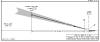
Glide Path: This equipment provides the aircraft with a glide angle -
usually 3 degrees. The Localizer and Glide Path combine to bring the aircraft to
a point where the aircraft is 50 feet high at the runway threshold (decision
point).
Markers:
1. The Outer Marker at approximately 5nm helps the a/c adjust its course and
height.
2. The Middle Marker is located at approximately 3500 feet and used similarly.
3. The Inner Maker at 1000 feet is used only for Category II operations.
Exceptions:
There are always exceptions and here are some main exceptions.
1. DME & GP (Distance Measuring Equipment & Glide Path) when it is impossible to
have Markers.
2. DME & Localizer when there is no GP for whatever reason.
3. Offset Localizer. In this case the Localizer is not on the runway centreline,
but offset and lined up to bring the aircraft over the threshold at decision
height. Decision height is 50 feet at threshold.
click to enlarge in new window
click to enlarge in new window
Localizer
The localizer is used to provide
lateral guidance to the aircraft and thus allows for tracking the extended
runway centreline. The localizer information is typically displayed on a course
deviation indicator (CDI) which is used by the pilot until visual contact is
made and the landing completed. The localizer radiates on a carrier frequency
between 108 to 112 MHz with 50 kHz channel spacing. This carrier is modulated
with audio tones of 90 Hz, 150 Hz, and 1020 Hz. The 1020 Hz tone is used for
facility identification.
Normal limits of localizer coverage
- Glide Slope
- Frequency range: 329.15 - 335 MHz.
- Housed in a building next to the runway.
- 2.5 - 3 degrees above horizon.
- Used on front course only.
- Signal is 1.4 degrees wide.
- Automatically received with LOC frequency.
- Marker Beacons
- ILS - outer and middle.
- LOC BC -- at FAF (BCM - back course marker)
- Outer marker (OM)
- Located 4-7 miles from runway.
- Indicates approximately where aircraft
will intercept the glide slope when aircraft is at the proper altitude.
- Signal -- continuous dashes (2 per
second).
- Purple light.
- Middle marker (MM)
- Signal -- alternate dot/slash.
- 3500' from landing threshold.
- Amber light.
- Back course marker (BCM)
- Signal -- 2 dots.
- White light.
- Located at FAF of LOC BC approach.
- Inner marker (IM)
- Signal -- 2 dots.
- White light.
- Located between middle marker and landing
threshold.
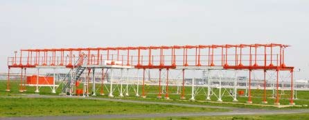
The localizer antenna array
radiates two different signals, carrier plus sideband (CSB) and suppressed
carrier sideband only (SBO). The CSB signal consists of the RF carrier amplitude
modulated (AM) with equal amplitudes of 90 Hz and 150 Hz tones. The SBO signal
is similar except that the carrier is suppressed. The localizer radiation
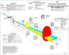
patterns are normally arranged so that the course sector of the proportional
guidance sector is symmetrical around the runway centreline (see figure).
If the aircraft on approach is
aligned with the runway centreline, the CDI will display no difference in the
depth of modulation (DDM) between the 90 Hz and 150 Hz audio tones; therefore,
the CDI needle is centred.
If the aircraft is to the right
of the centreline, the 150 Hz modulation will exceed that of the 90 Hz and
produce a deflection on the CDI towards the left. Conversely, if the aircraft is
to the left of the centreline, the 90 Hz modulation will exceed that of the 150
Hz and produce a similar but opposite deflection. This deflection corresponds to
the direction the pilot must fly to be aligned with runway centreline and is
proportional to the angular displacement from centreline.
The CDI has a full-scale
deflection of 150 microamperes where the DDM equals 0.155 in both the 90 Hz and
150 Hz directions. The angular displacement, or proportional guidance sector,
that corresponds to this full scale deflection is known as the localizer course
width. This width is typically tailored for a full-scale CDI deflection to occur
at 350 feet from runway centreline at threshold.
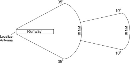
When the aircraft is outside
this course guidance sector, the CDI is required to provide full scale
deflection. This region is known as the clearance sector. The FAA requires that
this region extend from the localizer course edge out to 35 degrees on both
sides of centreline.
Reflected or scattered signals
that come from hangars and buildings historically and today pose the greatest
concern for establishing a localizer. These reflected signals cause quality
derogation of the on-course signal as seen by the aircraft. To minimize these
reflections, the common technique is to use larger array apertures that narrow
the localizer course beam and thus reduce the quantity of signals incident on
the reflecting surface.
In some cases, to maintain the
±35-degree clearance coverage, a separate RF carrier, offset from the course
frequency by 8 kHz, is radiated. Since these two signals fall within the
passband of the ILS receiver, the stronger of the signals is "captured" by the
receiver and is used for the guidance. These two-frequency localizer arrays are
called dual-frequency and are primarily used to support Category II/III
operations.
Glide Path
The glide slope provides the
pilot with vertical guidance. This signal gives the pilot information on the
horizontal needle of the CDI to allow the aircraft to descend at the proper
angle to the runway touchdown point. The glide slope radiates on a carrier
frequency between 329 and 335 MHz and is also modulated with 90 Hz and 150 Hz
tones. The glide slope frequencies are paired with the localizer, meaning the
pilot has to tune only one receiver control.
The radiation patterns of a
typical glide slope system are similar to those of the Localizer - if you
remember to rotate the pattern so that it is vertical instead of horizontal.
The null in the sideband-only (SBO) signal produces essentially a straight glide
path angle for the aircraft. The patterns are arranged so that 90 Hz modulation
predominates above the glide path and the 150 Hz modulation predominates below.
The glide path angle is normally
referenced at 3 degrees. If the aircraft is on this three-degree glide path,
equal amounts of the 90 Hz and 150 Hz are received and the CDI will be centred.
If the aircraft is above the glide path, the 90 Hz modulation exceeds that of
the 150 Hz and produces a deflection on the CDI downwards. If the aircraft is
below the established glide path, the 150 Hz modulation predominates and
produces a similar but opposite deflection. This deflection corresponds to the
direction the pilot must fly to intercept the glide path and is proportional to
the angular displacement from the glide path angle. As with the localizer, the
full scale deflection is 150 microamperes. Typically, the glide slope
sensitivity is set so that the full-scale indications occur at approximately 2.3
and 3.7 degrees elevation.
The FAA presently maintains five
types of glide slope systems. They are the null-reference, sideband-reference,
capture-effect, endfire, and waveguide. The null-reference, sideband-reference,
and capture-effect glide slope systems use the terrain in front of the antenna
mast to double, effectively, the vertical aperture of the radiating system and
produce the path in space. These three systems are typically referred to as
image glide slope systems. Where the ground plane in front of the glide slope
mast is irregular or absent, endfire or waveguide types are used. These systems
are called non-image and do not rely on the terrain to form the path in space.
Marker Beacons
Inner, Middle, and Outer
Marker beacons are used to alert
the pilot that an action (e.g., altitude check) is needed. This information is
presented to the pilot by audio and visual cues. The ILS may contain three
marker beacons: inner, middle and outer. The inner marker is used only for
Category II operations. The marker beacons are located at specified intervals
along the ILS approach and are identified by discrete audio and visual
characteristics (see Table 1). All marker beacons operate on a frequency of 75
MHz.
Marker Beacon Characteristics
| Marker Beacon |
Pilot Alert |
Distance to Threshold |
Modulated frequency |
Audio Keying |
| Outer |
Glide Path Intercept |
4 to 7nm |
400Hz |
------ |
| Middle |
Category 1 Decision Height |
3500 ft |
1300Hz |
.-.-.- |
| Inner |
Category 2 Decision Height |
1000 ft |
3000Hz |
...... |
Table table 1
The marker beacon coverage
provides adequate signal laterally throughout the localizer proportional
guidance sector. Marker beacons produce cone or fan-shaped radiated patterns
directed upward and, therefore, pose very few siting problems. The majority of
problems in locating the marker beacon are the availability of real estate and
access to utilities. If an acceptable site for the outer marker cannot be found,
an alternative is to collocate a Distance Measurement Equipment (DME)
transponder with the localizer. This DME then provides the range indication to
the aircraft. The ILS models do not provide any information with regard to
marker beacon performance. |
