general
VHF Omni-directional Radio Ranges [VORs] operate in
the Very High Frequency aviation navigation [NAV] band between 112.1 and 117.9
MHz. As VHF transmissions are line-of-sight the ground to air range depends on
the elevation of the beacon site, the height of the aircraft and the power
output. The VOR beacons are usually located at airfields but as they serve to
define designated air routes [ airways] some are located away from airfields,
often on high ground.
A simplified concept of the ground beacon is that it simultaneously transmits
two signals, a constant omni-directional signal called the reference phase and a
directional signal which rotates through 360°, during a 0.03 second system
cycle, and consistently varies in phase through each rotation. The two signals
are only exactly in phase once during each rotation – when the directional
signal is aligned to magnetic north.
Imagine a wheel with 360 spokes, at one degree azimuth spacing, with the VOR
beacon being the hub. The spokes are numbered clockwise from one to 360 and each
spoke or radial represents a magnetic bearing from the VOR beacon.
The airborne navigation circuitry measures the phase angle difference between
the directional signal phase received and the reference signal phase and
interprets that as the angular, or 'radial', indication currently being
received. Radials are identified by magnetic bearing – e.g. the 30° radial – and
thus form the basis for VOR, and designated air route, navigation. Essentially
the system indicates a line of position, from the selected VOR, on which the
aircraft is located at any time.
The beacon also transmits a Morse code aural identification signal at about 10
second intervals.
The airborne system utilising the VOR beacon transmissions usually consists of
an antenna (probably a V - type dipole mounted horizontally on the fin or
fuselage but could be the more expensive 'blade' or 'towel rail' types), a
conventional VHF receiver (if combined with the VHF communications
transceiver it is then called a NAV / COMM unit), navigation
circuitry and the separate panel mounted navigation indicator or 'Omni Bearing
Indicator' [OBI].
Some hand held aviation COMMS transceivers can also receive the NAV band VOR
transmissions and appear to have some navigation circuitry but, from all
reports, their VOR navigation capability, if it exists at all, is limited.
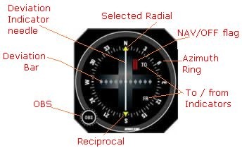
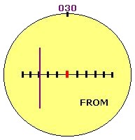
Basic Omni Bearing Indicator, like this Bendix-King model,
has a manually operated radial or 'omni bearing' selector [OBS] which
rotates an azimuth ring marked from 0° to 355°. The OBS selected radial is
indicated by the arrow at top dead centre and the reciprocal bearing is
indicated by the bottom arrow. The other features of a basic OBI are the
TO–FROM indicators, a deviation bar, a deviation indicator needle and a
NAV/OFF alarm flag.
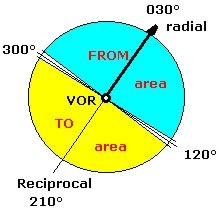
The TO–FROM indications on the OBI are dependent on the
aircraft's position relative to a notional ground baseline, formed perpendicular
to the selected radial and passing through the beacon site. Unlike the NDB
the indication is completely independent of the aircraft's heading. The
navigation circuitry compares the difference between the radial being received
and the radial selected. If the aircraft is located anywhere within range on the
radial side of the baseline the 'FROM' indication will be displayed on the OBI
and, if located within range on the reciprocal side, the 'TO' indication will be
displayed. For example if the 030° radial is selected on the OBI, the ground
baseline is established between 300° and 120°. If the radial received indicates
the aircraft is anywhere in the blue shaded area of the diagram and no matter
whether it is headed towards or away from the VOR, or in any direction
whatsoever, the OBI will display 'FROM'. Similarly if it is in the yellow area
the OBI will display 'TO' no matter which direction the aircraft is headed.
There are two areas of ambiguity – near bearings at right angles to the radial
(e.g. shown at 120° and 300°) – where the OBI will give fluctuating indications,
or display the 'OFF' flag.
The deviation bar and the deviation indicator needle together
form the Course Deviation Indicator or CDI. If the needle is over the
centre point the aircraft is then located at some position along the selected
radial – or its reciprocal. The five division marks or dots either side of the
centre point are spaced at two degree intervals, thus if the needle is over the
third mark, left or right of centre, the aircraft is positioned at a radial six
degrees in azimuth from the selected radial, or its reciprocal. (Actually the
aircraft is at the centre mark and the needle indicates the position of the
selected radial). Full travel of the needle from the centre to either side
represents 10° – or more – of azimuth. The ambiguity of whether the OBS
selection is the radial or the reciprocal is determined by the TO / FROM
indication; in the diagram at left 030 must be the radial as the aircraft is in
the FROM area. When the aircraft passes overhead the beacon the needle will
swing from side to side, the alarm flag may temporarily indicate that navigation
is 'OFF' and the TO/FROM indication will reverse.
A difficulty for a non IFR trained pilot using the VOR is a
lack of perception of which way to turn the aircraft to fly to a selected
radial, using the CDI indications. However, for VFR purposes, this is easily
ascertained if the pilot follows two simple rules:
1. To track FROM a VOR select the radial required and ensure FROM is indicated.
2. To track TO a VOR rotate the OBS until the CDI is centred and TO is
indicated.
In both cases as wind effect drifts the aircraft off track the deviation
indicator needle will move to one side and that movement indicates the direction
to turn to regain track. i.e. turn towards the needle.
VOR applications
Like the NDB / ADF there are several applications for the VOR in light aircraft
cross country VMC navigation. The applications briefly described below will be
detailed in the 'Using the VOR' module.
Homing & tracking to a VOR. Even with a crosswind component tracking toward a
VOR is quite simple, rotate the OBS until the CDI is centred and TO is
indicated, turn onto that magnetic heading and then just keep the CDI centred
and you will track more or less direct to the VOR.
Tracking from a VOR. Rotate the OBS to the required track [radial], ensure FROM
is indicated, turn onto that magnetic heading and just keep the CDI centred and
you will maintain the track.
Position fixes. If two VORs are in range then the bearing from each can be
ascertained, roughly plotted on the chart [after converting to true bearings]
and the aircraft position will be close to the intersection point of the LOPs.
Alternatively a VOR bearing and a NDB bearing can be used or a VOR bearing and a
line feature on the chart, the latter technique being the most frequently used.
Running fix / distance from VOR. The 1-in-60 rule can be applied when the
aircraft is within range of a transmitter by turning the aircraft so that the
station is abeam and then measuring the degrees traversed against time, as in
the NDB running fix application above. The advantage with the VOR is that the
CDI needle indicates the degrees traversed. As in the NDB application the
position fix is the distance along the second radial from the beacon.
VOR errors
Standard VOR systems are more accurate than NDB / ADF but are still subject to
errors at the ground station, bending distortion of signals caused by terrain
effect and avionics errors. The aggregation of all errors is very unlikely to
exceed 5°.
Though very thin on the ground in the outback areas of Australia, NDB and VOR
can be very useful, provided the aircraft is within range, but not the best
value for money. That distinction now belongs to another, and more advanced,
supplementary navigation tool – the Global Positioning System.
Navigating directly to a VOR is the easiest way to use this
kind of navaid.
-
Dial in the frequency of the VOR into your NAV1 radio
-
Turn the OBS (course selector knob) for the instrument(OBI)
until you see the word "TO" and the CDI
needle centres
-
Note the heading shown at the top of the instrument; fly
that course to go directly to the VOR
That's basically all there is to it! There are complications
such as crosswinds that will affect your ability to get to the VOR. If you have
winds you will have to adjust for them and fly a heading that will allow you to
follow the proper course.
In an ideal situation you could fly the heading you just
determined right to the VOR station. In that case the needle on the OBI would
remain centred right up until the time when you passed over the VOR. More
likely, though, your course will drift off to the side. By watching the needle
on the OBI you can see this happen and also tell how to adjust your heading to
get back on course:
try this excellent programme by Tim Carlson
| Control |
Function |
|---|
| Mouse |
Click/Drag on the Map |
Move the airplane, the transmitters, or change the wind vector (if in wind mode) |
|---|
| | Click the Buttons |
Change the vector (OBS) for the instrument (except the RMI, DG) |
|---|
| Keyboard |
Up & Down Arrows |
Increase or decrease the airplane
speed (60-300 kt - my future Lancair IVP) |
|---|
| | Left and Right Arrows |
Increase or decrease turn rate (deg/sec) |
|---|
| | Space Bar |
Instantly set the turn rate to zero |
|---|
| | Enter |
Reposition transmitters to original positions -
useful if you've moved them off the map |
|---|
| | R |
Toggle radials on & off (dark
colours = from side of VORs, light colours = TO side of VORs) |
|---|
| | 1 or 2 |
Switch instrument 1 or 2 between VOR, HSI, ADF,
RMI, DG, or Text |
|---|
| | W |
Toggle Wind mode (shown in status line) - when in wind mode you can click/drag on the map to change the wind vector |
|---|
| | P |
Pause the animation (wind and airplane motion) - you
can still rotate the instruments and drag the plane |
|---|
| | T |
Trace - start/stop a trail of dots showing the airplane's path |
|---|
| | H |
Hide - stop/start displaying the airplane and trace |
|---|
| | L |
Lost - randomly reposition the airplane on the map - most useful when the plane is hidden |
|---|