
the jet engine components
inlets
All turbine
engines have an inlet to bring free stream air into the
engine. The inlet sits upstream of the compressor and, while
the inlet does no work on the flow, there are some important
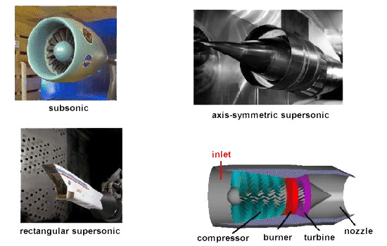
design features of the inlet. As shown in the figures
above, inlets come in a variety of shapes and sizes with the
specifics usually dictated by the speed of the aircraft.
subsonic
inlets
For aircraft
that cannot go faster than the speed of sound (like large
airliners), a simple, straight, short inlet works quite well.
On a typical subsonic inlet, the surface of the inlet, from
outside to inside, is a continuous smooth curve with some
thickness from inside to outside. The very front (most
upstream portion) of the inlet is called the highlight,
or the inlet lip. A subsonic aircraft has an inlet with
a relatively thick lip.
supersonic
inlets
An inlet for a
supersonic aircraft, on the other hand, has a relatively sharp
lip. The inlet lip is sharpened to minimize the performance
losses from shock waves that occur during supersonic flight.
For a supersonic aircraft, the inlet must slow the flow down
to subsonic speeds before the air reaches the compressor. Some
supersonic inlets, like the one at the upper right, use a
central cone to shock the flow down to subsonic speeds. Other
inlets, like the one shown at the lower left, use flat hinged
plates to generate the compression shocks, with the resulting
inlet geometry having a rectangular cross section. This kind
of inlet is seen on the F-14 and F-15 fighter aircraft. There
are other, more exotic inlet shapes used on some aircraft for
a variety of reasons.
inlets
efficiency
An inlet must
operate efficiently over the entire flight envelope of the
aircraft. At very low aircraft speeds, or when just sitting on
the runway, free stream air is pulled into the engine by the
compressor. In England, inlets are called intakes,
which is a more accurate description of their function at low
aircraft speeds. At high speeds, a good inlet will allow the
aircraft to manoeuvre to high angles of attack and sideslip
without disrupting flow to the compressor. Because the inlet
is so important to overall aircraft operation, it is usually
designed and tested by the airframe company, not the engine
manufacturer. But because inlet operation is so important to
engine performance, all engine manufacturers also employ inlet
aerodynamicists.
compressors
All turbine engines have a
compressor to increase the pressure of the incoming air
before it enters the combustor.
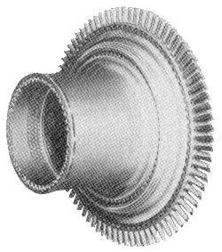
As shown in
the above figure, there are two main types of compressors:
axial and centrifugal. The compressor on the left is called an
axial compressor because the flow through the compressor
travels parallel to the axis of rotation. The compressor on
the right is called a centrifugal compressor because the flow
through this compressor is turned perpendicular to the axis of
rotation. Centrifugal compressors, which were used in the
first jet engines, are still used on small turbojets and
turboshaft engines and as pumps on rocket engines. Modern
large turbojet and turbofan engines usually use axial
compressors.
An axial flow compressor
(stators omitted for clarity). This is the high pressure
compressor from a General Electric F404 engine
Why the change
to axial compressors? An average, single-stage, centrifugal
compressor can increase the pressure by a factor of 4. A
similar single-stage axial compressor increases the pressure
by only a factor of 1.2. But it is relatively easy to link
together several stages and produce a multistage axial
compressor. In the multistage compressor, the pressure is
multiplied from row to row (8 stages at 1.2 per stage gives a
factor of 4.3). It is much more difficult to produce an
efficient multistage centrifugal compressor because the flow
has to be ducted back to the axis at each stage. Because the
flow is turned perpendicular to the axis, an engine with a
centrifugal compressor tends to be wider (greater
cross-sectional area) than a corresponding axial. This creates
additional undesirable aircraft drag. Centrifugal compressors
are also less efficient than axial compressors. For all of
these reasons, most high compression jet engines use multi
staged axial compressors. But, if only a moderate amount of
compression is required, a centrifugal compressor is much
simpler to use.
The combustion chamber has the difficult task of burning large
quantities of fuel, supplied through fuel spray nozzles, with
extensive volumes of air, supplied by the compressor, and
releasing the resulting heat in such a manner that the air is
expanded and accelerated to give a smooth stream of uniformly
heated gas. This task must be accomplished with the minimum
loss in pressure and with the maximum heat release within the
limited space available.
The amount of fuel added to the
air will depend upon the temperature rise required. However,
the maximum temperature is limited to within the range of 850
to 1700 °C by the materials from which the turbine blades and
nozzles are made. The air has already been heated to between
200 and 550 °C by the work done in the compressor, giving a
temperature rise requirement of 650 to 1150 °C from the
combustion process. Since the gas temperature determines the
engine thrust, the combustion chamber must be capable of
maintaining stable and efficient combustion over a wide range
of engine operating conditions.
The temperature of the gas after
combustion is about 1800 to 2000 °C, which is far too hot for
entry to the nozzle guide vanes of the turbine. The air not
used for combustion, which amounts to about 60 percent of the
total airflow, is therefore introduced progressively into the
flame tube. Approximately one third of this gas is used to
lower the temperature inside the combustor; the remainder is
used for cooling the walls of the flame tube.
There are three main types of combustion chamber in use for
gas turbine engines. These are the the multiple chamber, the
can-annular chamber and the annular chamber.
Multiple chamber
This type of combustion chamber
is used on centrifugal compressor engines and the earlier
types of axial flow compressor engines. It is a direct
development of the early type of Whittle engine
combustion chamber. Chambers are disposed radially around the
engine and compressor delivery air is directed by ducts into
the individual chambers. Each chamber has an inner flame tube
around which there is an air casing. The separate flame tubes
are all interconnected. This allows each tube to operate at
the same pressure and also allows combustion to propagate
around the flame tubes during engine starting.
A
multiple combustion chamber
Can-annular chamber
This type of
combustion chamber bridges the evolutionary gap between
multiple and annular types. A number of flame tubes are fitted
inside a common air casing. The airflow is similar to that
already described. This arrangement combines the ease of
overhaul and testing of the multiple system with the
compactness of the annular system.
A
can-annular combustion chamber
Annular chamber
This type of
combustion chamber consists of a single flame tube, completely
annular in form, which is contained in an inner and outer
casing. The main advantage of the annular combustion chamber
is that for the same power output, the length of the chamber
is only 75 per cent of that of a can-annular system of the
same diameter, resulting in a considerable saving in weight
and cost. Another advantage is the elimination of combustion
propagation problems from chamber to chamber.
power turbine
The turbine has the task of
providing power to drive the compressor and accessories. It
does this by extracting energy from the hot gases released
from the combustion system and expanding them to a lower
pressure and temperature. The continuous flow of gas to which
the turbine is exposed may enter the turbine at a temperature
between 850 and 1700 °C which is far above the melting point
of current materials technology.
A high-pressure turbine
stage from a CFM56 turbofan engine
To produce the driving torque,
the turbine may consist of several stages, each employing one
row of stationary guide vanes, and one row of moving blades.
The number of stages depends on the relationship between the
power required from the gas flow, the rotational speed at
which it must be produced, and the diameter of turbine
permitted. The design of the nozzle guide vanes and turbine
blade passages is broadly based on aerodynamic considerations,
and to obtain optimum efficiency, compatible with compressor
and combustor design, the nozzle guide vanes and turbine
blades are of a basic aerofoil shape.
A turbine blade with
cooling holes
The desire to produce a high engine efficiency demands a high
turbine inlet temperature, but this causes problems as the
turbine blades would be required to perform and survive long
operating periods at temperatures above their melting point.
These blades, while glowing red-hot, must be strong enough to
carry the centrifugal loads due to rotation at high speed.
To operate under these conditions, cool air is forced out of
many small holes in the blade. This air remains close to the
blade, preventing it from melting, but not detracting
significantly from the engine's overall performance. Nickel
alloys are used to construct the turbine blades and the nozzle
guide vanes because these materials demonstrate good
properties at high temperatures.
nozzles
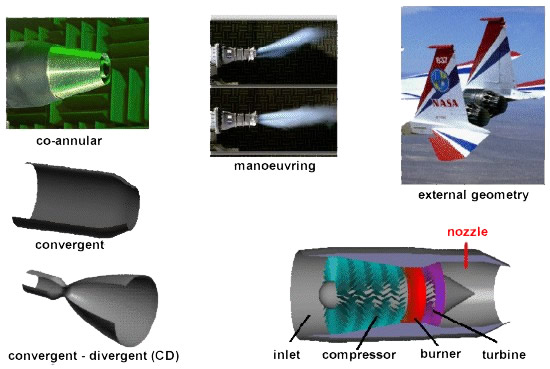
All gas turbine engines have a
nozzle to produce thrust, to conduct the exhaust gases
back to the free stream, and to set the mass flow rate through
the engine. The nozzle sits downstream of the power turbine.
A nozzle is a
relatively simple device, just a specially shaped tube through
which hot gases flow. However, the mathematics which describe
the operation of the nozzle takes some careful thought. As
shown above, nozzles come in a variety of shapes and sizes
depending on the mission of the aircraft. Simple turbojets,
and turboprops, often have a fixed geometry convergent nozzle
as shown on the left of the figure. Turbofan engines will
sometimes employ a co-annular nozzle as shown at the top left.
The core flow will exit the centre nozzle while the fan flow
exits the annular nozzle. Afterburning turbojets and turbofans
often have a variable geometry convergent-divergent (CD)
nozzle as shown on the left. In this nozzle, the flow first
converges down to the minimum area, or throat, then is
expanded through the divergent section to the exit at the
right. The variable geometry causes these nozzles to be heavy,
but provides efficient engine operation over a wider airflow
range than a simple fixed nozzle. Rocket engines usually have
a fixed geometry CD nozzle with a much larger divergent
section than is required for a gas turbine.
All of the
nozzles we have discussed thus far are round tubes. Recently,
however, engineers have been experimenting with nozzles with
rectangular exits. This allows the exhaust flow to be easily
deflected, as shown in the middle of the figure. Changing the
direction of the thrust with the nozzle makes the aircraft
much more manoeuvrable.
Because the
nozzle conducts the hot exhaust back to the free stream, there
can be serious interactions between the engine exhaust flow
and the airflow around the aircraft. On fighter aircraft, in
particular, large drag penalties can occur near the nozzle
exits. A typical nozzle-afterbody configuration is
shown in the upper right for an F-15 with experimental
manoeuvring nozzles. As with the inlet design, the external
nozzle configuration is often designed by the air-framer. The
internal nozzle is usually the responsibility of the engine
manufacturer.
|
