|

power
plant accessories
The development of power plant accessory equipment goes back
to a period immediately following the first World War, when
flying was a haphazard and dangerous occupation. The only
flight instruments were a compass, bubble, altimeter and
tachometer. With these instruments, flights were occasionally
made through clouds but not for protracted periods. Very few
pilots were capable of flying blind even for the shortest
period. After the World War and at the beginning of commercial
aviation and the inauguration of airmail service in this
country most of the flying was of the contact type. The
development of the turn and bank indicator gave the first real
help in blind flying. Then came the artificial horizon and
gyro compass. The development of the radio range beam and
directional radio made it possible and practical to fly
without contact with the ground. With these instruments
available, the art of blind flying developed rapidly and
increased to the point where experimental flights entirely
with instruments from "take-off" to landing have been
successfully conducted.
Similarly, the development of the single
engine airplane of the World War period, with its engine of 30
horsepower, to the huge multi-motored transport of today,
wherein the output of a single cylinder is often equal to or
more than the total output of the early engine, has brought
about the development of power plant accessory equipment to
its present stage. The days of engine starting, wherein the
propeller was pulled through by hand, have long since
disappeared to be replaced by electrically operated Inertia or
Direct Cranking Electric Starters capable of transmitting 1500
pound feet of torque for the cranking of engines rated up to
2000 horsepower.
In a like manner, the development of
generating equipment from the early wind driven types having
an output of approximately 50 watts, to the engine driven
types of 3000 watts capacity, has also taken place. In
addition, the Venturi tube, which was subject to clogging with
dirt and ice, has long since been replaced with engine driven
vacuum pumps with capacities sufficient to provide proper
suction for the operation of navigating instruments and
pressure for the operation of wing and tail surface de-icers.
Whether the need has been for aircraft engine starting or for
the generation of electric power, accessory units have proved
vital necessities to the operation of the present day air
transport and military airplane. Electric motors for the
operation of retractable landing gear, wing flaps, tail
wheels, etc.; hydraulic pumps, valves and control units for
actuating hydraulically, full feathering propellers,
retracting mechanisms, etc.; radio dynamotors for the
operation of radio receivers and transmitters; fuel flow
meters for determining fuel consumption; these are only a few
of the many accessory units which have played an important
part in the development and dependability of the present-day
airplane. To the old time pilot the airplane may have
consisted primarily of the airplane and its engine, but to the
experienced air transport pilot of today aircraft accessory
equipment and flight instruments play a major part in
establishing flight security.
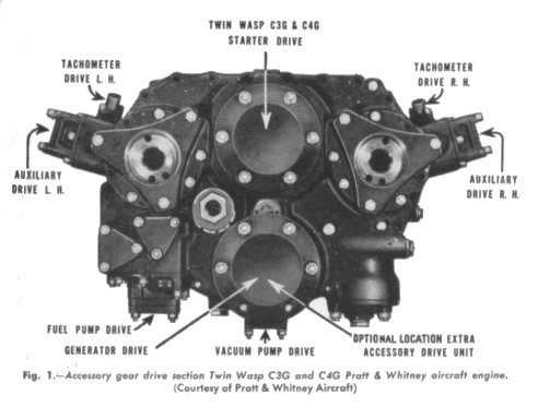
The fundamental requirements of any form of
aircraft power plant accessory are dependability, minimum
weight, simplicity of installation, ease of operation,
effectiveness, serviceability, and low initial cost. As the
number and type of power plant accessories are, necessarily,
limited to the number of drives available on the rear or
accessory drive section of the power plant, careful
consideration must be given to the number of operations to be
performed, and the type of
service to which the airplane is to be
subjected, prior to the selection of accessory equipment. In
addition, the capacity and type of accessory units to be
installed on a given power plant are definitely limited to the
physical characteristics, operating speed and torque
limitations of the accessory drives available.
Swinging the Prop
Although swinging the prop was the earliest
common form of starting for aircraft engines and the method
still in limited use for present-day light engines, there has
always been considerable danger to the operator when effecting
engine starting by this method. Swinging the prop, in most
cases, has been replaced by the use of either a hand turning
gear, air-injection starter, or direct cranking electric
starter, the latter two methods providing quick and convenient
starting by the pilot without need for external assistance.
The need for mechanical aid in starting, evolved many methods
which were short lived. Several, however, were successful to a
certain degree.
The Hucks Starter
An early advance in the development of
aircraft engine starting was the invention of the Hucks
starter, which was named after its inventor. This unit was an
external mechanical starter, employing a Ford motorcar
chassis. A special chain from the gearbox was made to drive a
layshaft mounted high up and adjustable. At the forward end of
this shaft was a coupling which could be made to engage with a
special "dogged" fitting attached to the propeller hub in the
same manner as a motor-car crank handle was used to engage the
engine crank shaft. Starting was effected by engaging the
coupling and rotating the layshaft. Disengagement of the
driving dog from the engine was automatic upon starting of the
engine. The Hucks starter, although an improvement over the
method of hand swinging was in turn, very impractical. Delays
in starting occurred when there were a large number of
airplanes to be started. Also, it was sometimes out of action
or did not exist at places where a start was required. At the
same time, it must be remembered that engines were increasing
in size and compression ratio to the point where swinging of
the propeller by hand as well as turning the propeller
mechanically by means of the Hucks starter were impracticable.
This brought about the development of the hand turning gear,
which is used in a modified form at the present time for
certain aircraft installations.
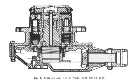
Hand Turning Gears
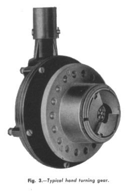
The development of the band turning gear
type of aircraft engine starter was primarily due to the need
for an aircraft engine starter capable of cranking engines
rated up to 600 horsepower not equipped with batteries or
generators. The hand turning gear consists, in general, of a
gear reduction unit, which operates an automatic engaging and
disengaging mechanism through an adjustable torque overload
release. Mechanical features are incorporated in the unit to
safeguard both the operator and starter from injury in case of
engine backfire. In case of the engine backfiring, the torque
overload release automatically disconnects the starter drive,
thus preventing damage to the starter mechanism. As a further
protection to the operator, a ratchet is provided in the hand
crankshaft to preclude the possible transmission of any
reverse motion to the crank-handle. Unusual care is exercised
in the design and manufacture of a hand turning gear to
eliminate friction, thereby assuring maximum even cranking. In
addition, the ratios of the gear reductions used have been
carefully determined in order to permit the highest engine
cranking speed consistent with the average manual effort which
can be expended in cranking. Thus, the operator is assured of
a prompt start with minimum effort, provided the other factors
which influence engine starting are normal.
 |
