|

aircraft engine
history
air-cooled aircraft engine
cylinders
by George Genevro
From the Past
Should aircraft engines be
liquid-cooled or air-cooled? This “difference of opinion” is
about a hundred years old and without a doubt the argument
will continue as long as piston engines power the airplanes we
fly. The manner in which the question is stated is misleading,
however, since all waste heat that comes through the structure
of an engine is eventually delivered to the air. In
“liquid-cooled” engines the coolant can be water, ethylene
glycol, a mixture of the two, or one of the many other liquids
that have been tried and found wanting. Its primary purpose is
to carry heat from the cylinder barrel and head to the
radiator through which air, the actual cooling medium, flows.
Proponents of liquid-cooling–now as in the past–can point to
some benefits and operational advantages such as lessened
hazard of shock cooling an engine, being able to direct
dedicated coolant flow to critical areas in the cylinder head
such as the exhaust valve seat and guide area, flexibility in
radiator placement, greater structural rigidity in the engine,
and having the option of designing airframes with a relatively
small cross-sectional area that could still house a powerful
engine. With every advantage, imagined or real, there is
almost always a price to pay. Those who opted for
liquid-cooled engines had to accept added weight, greater
possibility of battle damage in military applications, and
greater system complexity as the penalties. Such is life.
The general concept of
“liquid-cooling” an engine has remained basically the same
since before the Wright brothers made their historic flight,
except for some significant mechanical, chemical, and thermal
improvements. Those who chose to cool engines by the seemingly
simpler direct transfer of waste heat from the cylinder to the
air have had a much more tortuous and rocky path to follow,
generally speaking. The developers of effective air-cooled
engine installations had to, among other things, invent
effective engine cowlings, conduct extensive studies of the
aerodynamic behaviour of air inside a cowling and around
cylinders, and deal with myriad metallurgical and other
problems in the engine itself in order to extend the life of
critical components. Many choices had to be made with regard
to cylinder structure and arrangement, valve placement and
actuation, the number of valves per cylinder, and the ratio of
heat dissipation between the air and oil, to name but a few.
As in most engineering activities where there is not an
established body of information from which decision-making
assistance can be drawn, wrong choices were made that doomed
some promising engines and drastically extended the
development process of others. Probing the “edge of the
envelope” has never been for the faint of heart.
Inline and V-type engines.
Conceptually, the air-cooled cylinder has always been
associated with low weight and simplicity since no secondary
means of heat transfer was necessary. Pioneer engine designers
were well aware of this and one of the earliest successful
air-cooled aviation engines was the V-8 that Glenn Curtiss
used to power the June Bug in 1908. It reflected the
technology of that era and the individual cylinders with
integral heads were grey iron castings with relatively widely
spaced fins. The choice of gray cast iron as a cylinder
material was logical at that time. Its machining and wear
characteristics were relatively well understood since it had
been used extensively in manufacturing engines of all types.
Curtiss no doubt understood that aluminium would provide much
better heat transfer but it had been in commercial use for
only about 25 years and suitable alloys for producing dense,
strong, heat-treatable castings had not yet been developed.
Also, an aluminium cylinder would have required a cast iron or
steel sleeve, bronze or cast iron valve guides, and valve seat
inserts, making the construction of the engine considerably
more complex. While Curtiss no doubt also understood the value
of deep, closely spaced fins on air-cooled cylinders
regardless of the material used, foundry technology,
particularly the making of baked sand moulds and cores
necessary for such castings, had apparently not progressed to
the point that cylinders of acceptable quality could be cast
consistently.
European thinking tended to
follow the same trends with regard to materials and engine
layout. Renault in France introduced an air-cooled V-8 with
individual cast iron cylinders with integral heads in 1909.
Attempts to increase the power output of this engine brought
on drastic cooling problems that were only partly alleviated
by use of an engine-driven cooling fan. Larger versions of the
Renault engine in V-8 and V-12 form were developed and built
in France and also by the Royal Aircraft Factory in Britain
during World War I, but regardless of size the engines were
characterized by very short exhaust valve life and extremely
high fuel consumption. According to one author, (L.J.K.
Setright) these engines travelled a fine line between thermal
and mechanical disaster.
With the excellent vision
provided by hindsight one can see that the Renault and similar
engines were, to a considerable extent, fuel-cooled as a means
of extending the life of certain critical components,
particularly exhaust valves. This was a common characteristic
of practically all of the air-cooled in-line and V-type
engines of the World War I era. Specific fuel consumption on
the order of one pound. per horsepower per hour at full power
was not unusual. Incidentally, fuel cooling is not a
phenomenon limited to the distant past. Aircraft of the World
War II era powered by large radial engines generally left a
trail of black smoke when the engine was running at take-off
power, a certain indication that some of the fuel was not
completely burned. This generally served to keep cylinder head
temperatures within the prescribed limits and to cool exhaust
valves and other hot spots in the combustion chamber thereby
preventing detonation and/or pre-ignition.
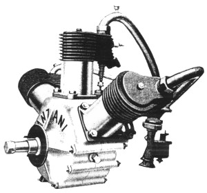
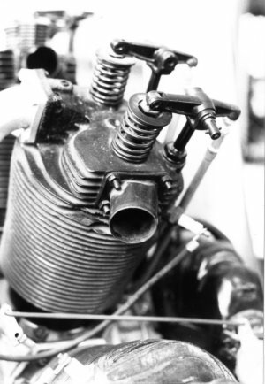
The unusual 3 cylinder Anzani engine that Louis Bleriot used
in his flight across the English channel had cast iron
cylinders with “atmospheric” intake valves and cam-operated
exhaust valves. Note the priming cup on the centre intake
tube.
In 1909, a year that has been
called “the year of practical powered flying” by some aviation
historians, the air-cooled three cylinder “fan type” Anzani
engine powered Blériot's monoplane on its epic 37-minute
flight across the English channel. This somewhat unusual
engine had cast iron air-cooled cylinders with
camshaft-operated exhaust valves and “atmospheric” intake
valves that were kept closed by light springs and opened in
reaction to the differential between atmospheric pressure and
lowered pressure in the cylinder as the piston moved down on
the intake stroke. It is surprising that this type of intake
valve arrangement was used in early aircraft engines such as
the Anzani when in practically all automotive engines of that
era both the intake and exhaust valves were cam-operated. It
did, however, eliminate one pushrod and rocker arm per
cylinder, simplify the cam, and save weight.
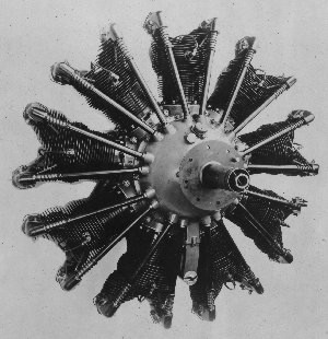
Rotary radial engines. Direct
air cooling was the natural choice for the designers of the
rotary radial engines used extensively in World War I military
aircraft. The machining capability necessary to produce the
cylinders was readily available, and the major parts of the
engine were machined from billets and forgings of alloy steel
rather than from castings. The materials were very likely one
of the low-to-medium carbon steels alloyed with nickel that
were popular in that era. The first of the well-known French
rotaries, the 50 horsepower Gnome, had been flown successfully
in 1909. The power-to-weight ratio of the rotaries was
generally better than that of other aircraft engines, a fact
that made them attractive to aircraft designers. In response
to military needs, larger rotary engines were manufactured in
relatively large quantities in Germany as well as in France
and Britain. Some rotary engines were manufactured in the U.S.
under license agreements with the French. Near the end of
World War I some twin-row fourteen and eighteen cylinder
rotaries had been designed and tested but it is doubtful that
any of these were used operationally.
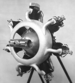
The cylinders of the Le Rhone rotary engine of early World War
I vintage were machined from steel billets and had relatively
closely spaced fins. The single pushrod operated both the
intake and exhaust valves by means of a semi-desmodromic cam
ring.
Since the typical rotary engine
used in World War I fighters turned at about 1,200 RPM at full
power and was enclosed in a partial cowling, the relatively
shallow fins machined as an integral part of the cylinder were
adequate for heat dissipation. The cylinder walls were quite
thin and the head was usually an integral part of the
cylinder, resulting in a clean, simple, and light structure.
There were no exhaust manifolds on rotary engines and when the
exhaust valve on top of the head was open the exhaust gases,
which generally contained liberal amounts of castor oil,
vented directly to the atmosphere inside the partial cowling
used on tractor installations such as the Nieuport and Sopwith
aircraft. Since there was no way to incorporate an oil sump or
any sort of an oil recovery system into the structure of the
engine, the lubrication system inevitably was of the “total
loss” type.
While the rotary radial engine
was quite satisfactory for certain specialized military uses,
its idiosyncrasies–and there were many–made it unsuitable for
commercial applications. By the end of World War I it was
considered obsolete. One of its major drawbacks was that in
operation it produced gyroscopic forces that were a challenge
to many pilots–and a death warrant to some–when controls were
actuated to change the aircraft's direction of flight. Another
basic disadvantage of the rotary engine was that the windage
losses were quite high because of air resistance to the motion
of the cylinders as they rotated. After World War I, surplus
rotaries were readily available but efforts to convert them to
static radial engines were generally unsuccessful since
cylinder head and exhaust valve cooling were very inadequate
unless the cylinder was moving rapidly through the air. Today,
the only operators of rotary engines are dedicated restorers
of World War I aircraft and builders of replicas who strive
for maximum authenticity.
Static Radial Engines. By the
middle years of World War I a number of engine designers in
England had come to the conclusion that the static radial
engine layout offered the best path to developing militarily
and commercially viable engines. There was also support for
the development of air-cooled engines from the British Navy
since Admiralty planners were convinced that such engines
would be lighter for a given power output, easier to maintain,
and less subject to battle damage, a matter of more than
passing interest to pilots flying single-engined aircraft over
water. Incidentally, U.S. Navy planners and aviators came to
essentially the same conclusions in the very early 1920s.
While there was some interest the 1930s and early 1940s in
liquid-cooled engines such as the experimental Lycoming
XH-2470 and Pratt & Whitney XH-3730, a 24 cylinder sleeve
valve engine, it was of short duration. In the U.S. Navy, the
air-cooled radial engine would reign supreme throughout World
War Il and beyond in piston-engined aircraft
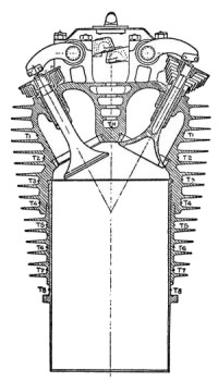
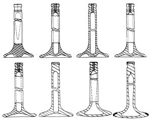
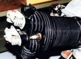
The cylinder developed by Prof. A. H.
Gibson and Sam Heron at the Royal Aircraft Establishment in
1918 had many modem features, including a mercury-cooled
exhaust valve and an aluminium head with relatively deep fins.
Note the unusual valve springs.
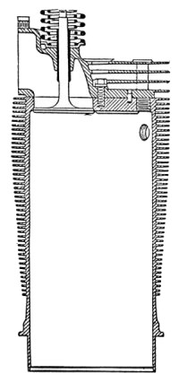
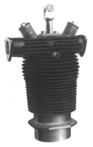
The closed-end poultice type cylinder
barrel of the British ABC Dragonfly engine built in
1918 was made of steel and the head was held in place with cap
screws and studs. The intake valve is shown.
During World War I British
military planners and others who saw the need for engines that
could be used in both military and commercial applications had
come to the conclusion that cast iron cylinders were
inadequate. The Royal Aircraft Factory (later called the Royal
Aircraft Establishment), Britain's primary aviation research
facility at the time, was directed to develop new cylinder
designs. Professor A. H. Gibson and Samuel D. Heron, two men
who would have a profound effect on the evolution of the
air-cooled aircraft engine cylinder, were hired. Both
understood that aluminium transmitted heat well and decided
that the head of the cylinder and some of the cylinder barrel
fins should be aluminium castings and that the wear surface of
the cylinder barrel should be a cast iron or steel sleeve.
Bolted joints between the head and barrel were avoided because
of the possibility of gasket failure and leaks in service, a
matter that the manufacturers of the Kinner, Warner, and other
small radials in the U.S. should not have ignored.
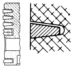
By 1918 Heron and Gibson had
designed, manufactured, and tested cylinders that consisted of
open-ended machined steel barrels with an external thread on a
portion of the upper end and a mounting flange on the lower
end. The finned cast aluminium head, which was fitted with
valve seat inserts and valve guides, was internally threaded.
The pitch diameter of the internal thread on the head was
slightly smaller than that of the external thread on the
cylinder barrel so that the head had to be heated in order to
allow assembly. This resulted in a joint that was mechanically
secure at the cylinder's operating temperature and provided
the best escape path for waste heat. In concept, if not in
exact detail, the modem air-cooled cylinder had arrived, but
not everyone was ready to accept it, possibly because of the
“not invented here” syndrome prevalent in some companies.
Some British makers of air-cooled
engines, apparently not realizing what the genius of Prof.
Gibson and Mr. Heron had brought them, cast their lot with
what was known as the “poultice” head design for air-cooled
cylinders. The cylinder barrel was machined from a steel
billet or forging with a flat, closed top end that had
openings that served as valve seats, as in the case of the
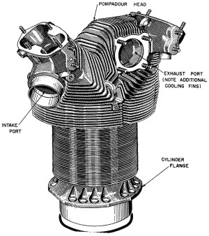
unfortunate ABC cylinder. The early Bristol Jupiter
(formerly the Cosmos) was a poultice head engine. On the early
Jupiters, four valves with parallel stems were used,
with the two exhaust valves at the front of the cylinder and
the intakes at the rear. The choice of four relatively small
valves rather than two large ones very likely stemmed from the
belief that the smaller valves would run at lower temperatures
and therefore last longer. The pushrods, rocker arms,
and valve springs were exposed and parts such as the rocker
arm pivot bearings required frequent greasing.
A cast aluminium head that
incorporated the valve ports, valve guides, and rocker arm
stands was attached to the top of the steel cylinder with
bolts or studs. Since the fin area on the Jupiter head
was quite limited, heat transfer from the combustion chamber
to the air was poor and the head required frequent re-bedding
to the cylinder. Engines using this arrangement were never
completely satisfactory although they were widely used in a
number or British and other European aircraft. The Jupiter
was manufactured under license in a number of other nations.
Since poor exhaust valve cooling and relatively short valve
life had been a continuing and vexing problem, the acerbic Sam
Heron once stated that Jupiter consumption should be
stated in terms of pounds of exhaust valves rather than in
pounds of fuel per horsepower/hour.
During the 1920s the Jupiter
cylinder design was subjected to intensive development. Partly
because of experiments with turbo-superchargers on the
Jupiter IV and the introduction of geared internal
superchargers in 1926, it became clearly evident that the
poultice head was inadequate. Bristol finally gave up on the
poultice head design and converted to a variant of the
Gibson/Heron type cylinder at this time and retained the four
valve per cylinder arrangement but with inclined valves in a
pent-roof combustion chamber. It is interesting to note that
the poppet valve Bristol radials were the only radial engines
produced in any quantity that had four valves per cylinder. In
an interesting mixture of old and new technology, the World
War II era Bristol radials such as the Mercury had
partially exposed rocker arms and valve springs mounted atop
forged aluminium heads with machined fins and sodium-cooled
exhaust valves and also had forged aluminium pistons.
Developments
in the U.S.
The Lawrance-Wright Era.
In the U.S., almost the only
proponent of the air-cooled engine during World War I was the
Lawrance Aero Engine Company. This small New York City firm
had produced the crude opposed twins that powered the Penguin
trainers, which were supposed to be the stepping-stone to the
Jenny for aspiring military pilots. The Penguins were not
intended to fly but apparently could taxi at a speed that
would provide some excitement for trainees as they tried to
maintain directional control and develop some feel of what
flight controls were all about. The Lawrance twins, which can
be seen in many museums, had directly opposed air-cooled
cylinders and a crankshaft with a single crankpin to which
both connecting rods were attached. This arrangement resulted
in an engine that shook violently at all speeds and was
therefore essentially useless for normal powered flight. After
World War I, some attempts were made, generally unsuccessful,
to convert the Lawrance twins into usable engines for light
aircraft by fitting a two-throw crankshaft and welding an
offset section into the connecting rods. This proves that the
desire to fly can be very strong indeed in some individuals.
The
cast aluminium cylinder head on the Lawrance opposed twin
engine used on the World War I “Penguin” trainers was attached
to the cylinder with studs. Note the unusual hairpin valve
springs and the adjustable length pushrods.
The hairpin valve
springs pictured on the left were possibly pioneered by
Salmson in 1911, and later used not only on British
single-cylinder racing motorcycle engines, but also by Ferrari
and others into the 1950s. This use was a response to the same
problem that led to desmodromic valves at Ducati, Norton (test
only) and Mercedes - namely the fatigue of coil springs from
"ringing". Hairpin springs ran cool because they were exposed,
and they were less subject to fatigue. They could also be
changed without engine disassembly. Around 1964 cleaner steels
produced by vacuum re-melting became available in quantity,
making possible the manufacture of highly fatigue-resistant
spring wire. Previous wire was made from electric furnace
steel - then the cleanest available. Vacuum remelted steel
wire made desmo and hairpins redundant. Today Ducati engineers
respond to the question "Why still desmo?" much as Bosch
engineers did to the 1945 question "why direct injection when
carbs were so much simpler?". They said that once they'd
started down that road, it was simpler to continue rather than
start over with another technology.
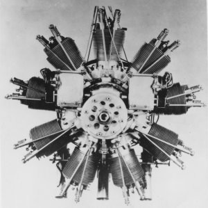
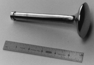
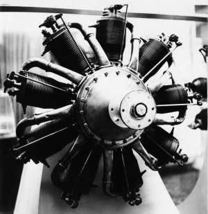
The Lawrance J-1 was the best American
air-cooled engine when it passed its 50-hour test in 1922.
After the end of World War I, the
Lawrance engineers worked with both the Army and the Navy in
developing a nine-cylinder radial engine, the Model J-1.
It was the best American air-cooled engine at the time and
passed its 50-hour test in 1922. A unique feature of the
engine was the use of exhaust valves with hollow stems that
were partly filled with mercury as a means of carrying heat
from the head of the valve through the stem to the valve
guide. Heron and Gibson had experimented with hollow stemmed
valves for a number of years using water or mercury as heat
transfer agents. The use of mercury was not really
satisfactory since it would not wet the surface of the inside
of the valve stem and therefore did not transfer heat well.
Water had been found to be wholly unsuitable.
The early 1920s Wright-Lawrance radial
engine had exposed overhead valves. Note the roller tips on
the rocker arms, adjustable pushrods, and Alemite grease
fittings on the rocker arm pivots.
The U.S. Navy had decided to
build aircraft carriers and since it badly needed light,
reliable engines it gave a contract to Lawrance for the J-1
radial and ceased buying the liquid-cooled Hispano-Suiza
engines manufactured by Wright under license as a means of
pressuring Wright and other companies into developing radial
engines. The Wright Aeronautical Corporation bought the
Lawrance Company, largely at the urging of the Army and Navy,
and the later engines were known as Wrights. These engines,
known as the J series, were dominant in the 1920s and the J-5,
which was the first American production engine to use
salt-cooled exhaust valves, achieved everlasting fame as the
powerplant that carried Charles Lindbergh across the Atlantic.
Samuel Heron, ever on the move,
had emigrated to the U.S. in 1921 after a disagreement with
his employer, J.D. Siddeley of the Siddeley Deasy Company,
over Siddeley's efforts to alter one of Heron's cylinder
designs. It has been said that Heron did not suffer those he
considered fools gladly-or at all- and apparently he did not
make exceptions for employers or company owners. After his
arrival in the U.S. he went to work for the U.S. Army Air
Service at McCook Field (now Wright-Patterson AFB) in Dayton,
Ohio as a development engineer. In 1926, he joined the Wright
Company, of which Lawrance was now vice-president, and his
work in cylinder development was largely responsible for the
success of the Wright J-5 engine. The Lawrance cylinder design
had evolved from an all-aluminium cylinder with a steel liner
that suffered from breakage of the aluminium mounting flange
to the J-5 type that had a finned steel cylinder barrel with a
screwed-on head and much more fin area, especially around the
exhaust valve port. A major step had been taken in improving
the radial air-cooled engine but much remained to be done.
Pratt & Whitney set a new standard for
cylinder design with its first engine, the Wasp
A New Player in the Horsepower
Race. Pratt & Whitney set a new standard for cylinder design
when their first engine, the Wasp (which we now know as the R-
1340 in its military designation) was introduced in 1926. It
incorporated the best features of Heron's latest cylinders and
improvements such as integral rocker arm housings and
additional fin area. That some of the best features of the
Heron cylinder design should appear in this new engine is not
surprising since Pratt & Whitney was formed by F. B.
Rentschler, who had resigned as president of Wright in 1925.
George Mead, Wright's former Chief Engineer, and Andrew
Willgoos, Assistant Chief Engineer for Design, left Wright to
assume similar positions at Pratt & Whitney. The Wasp was an
immediate success and the Navy, by now heavily committed to
building a carrier force, ordered 200 engines, an especially
large order for that era. Almost immediately, the Navy
expressed a need for a larger engine and the 1,690 cubic inch
Hornet was designed and built, passing its Navy type test in
1927. The horsepower race had started in earnest.
Wright responded to this
challenge with an even larger engine, the 1,790 cubic inch
single row direct-drive nine cylinder Cyclone. Its
displacement was soon increased by 30 cubic inches and as the
R-1820, it powered a number of military and civilian aircraft.
Its rated power output rose from about 500 horsepower in 1927
in its original direct-drive form to as much as 1,525
horsepower in the versions produced after World War II. The
author clearly remembers an instance in the early 1980s during
forest fire season when a heavily loaded (very probably
overloaded) ex-Navy Grumman S2F “borate bomber” took off from
the Ramona Airport in southern California on a fairly hot day.
The rate of climb was minimal but the sound of the two very
hard-working Wright R-1820s echo off the surrounding hills was
memorable.
The unique Comet engine, manufactured in
Wisconsin in 1929, had a semi-desmodromic valve actuation
system that required only one push rod and one rocker arm. The
cam ring follower was similar to that used on the LeRhone
rotary engines. Note the fore-and-aft alignment of the valves.
The power output of other engines
that were developed during the World War II period was also
increased substantially. This can be attributed largely to
advances and innovations in cylinder design and construction,
metallurgical progress, and improvements in foundry capability
in the U.S. American foundry men, through intensive
experimentation, had developed procedures for casting thin,
closely spaced fins on a production basis and had progressed
well beyond the British in this critical area. One cannot help
but be impressed, in looking at a World War II era Pratt &
Whitney or Wright engine, at the skill of those who produced
those beautiful cylinder head castings literally by the
hundreds of thousands, and in some cases, by the millions.
The Comet cylinders had the
head cast integrally with the barrel and had a hemispherical
combustion chamber. Note the single rocker stand and the
short, simple ports.
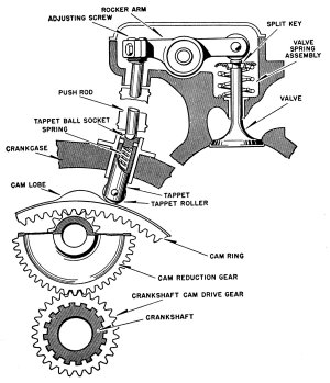
By the early 1930s, cylinder
design in the U.S. for large radial engines had become
somewhat standardized, with bores of about six inches and two
large valves per cylinder in a hemispherical combustion
chamber. Valve actuation was by means of ring cams housed in
the nose section or the crankcase, enclosed push rods, and
rocker arms in individual housings cast integrally with the
cylinder head. While all engines of any consequence had
enclosed valve mechanisms, it wasn't until 1932 that automatic
pressure lubrication with engine oil was introduced on the
Pratt & Whitney Wasp. Much of the subsequent development work
involved experimentation with materials, sodium-cooled valves,
improvements in piston rings, better foundry practices, and
many other minor improvements that would extend engine life
and allow higher power outputs. Near the end of World War II
the much more widespread use of forged cylinder heads with
machined fins was a major factor in allowing engines to be
operated at higher manifold pressures because of the greater
mechanical strength and better heat dissipation capabilities
of such heads.
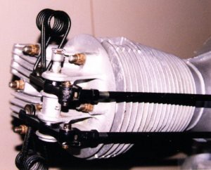
The cast aluminium head on this late
1930s Kinner engine was attached to the steel barrel by a ring
of studs and nuts. The valve mechanism was enclosed (rocker
covers have been removed).
Engine development has always
been a long, often unrewarding, and always expensive process
that can often be affected by events beyond the designer's
control, such as limited finances or a major war. One of the
inescapable conditions imposed by war is that survival and
victory often depend on the ability to adapt and change
rapidly to meet new challenges. In the late 1930s and
throughout World War II military necessity made performance
the dominant concern, and when cost became a secondary factor
progress was almost inevitably more rapid. The more rigorous
operating conditions revealed weaknesses in cylinders and many
other engine parts that might have remained hidden in normal
commercial use, and by the end of the war the air-cooled
cylinder had very nearly reached its peak in both performance
and durability. Other than direct fuel injection, which came
into relatively limited use in the last years of World War II
and allowed much more accurate fuel-air mixture distribution,
no major innovations appeared since it was becoming
increasingly evident that large radial engines were no longer
of major importance in commercial or military aviation. The
gas turbine had arrived and a new era had begun.
Materials
and Processes, Small Air-Cooled Engines
materials
and processes
Materials and how they were
processed played a major role in the evolution of the
air-cooled cylinder and it was fortunate that the science and
practice of metallurgy had made rapid strides during the
critical periods of cylinder development. Cyclic mechanical
stresses and the process of waste heat dissipation are the two
main enemies of the aircraft engine. Metallurgical and
mechanical improvements were prime factors in extending
cylinder life. The magnitude of the problem was well stated by
an engine developer many years ago who, probably while viewing
some failed parts, described the aircraft engine as a machine
bent on destroying itself mechanically while busily trying to
incinerate its exhaust valves.
exhaust valves
This was definitely the most
trouble-prone and vexing part of the air-cooled aircraft
engine. All engine designers made serious efforts to improve
exhaust valve reliability and durability. Experiments with
internally cooled valves were started as early as 1913.
Initially, water and mercury, as previously stated, were tried
as the heat transfer agents in the sealed, hollow valve stems.
While the material in the stems was almost always called a
coolant, in actuality it was a heat transfer agent used to
carry heat from the head of the valve to the stem where it
could be passed through the valve guide and into the fins on
the cylinder head. As mentioned earlier, water proved to be
impractical and mercury did not work well because it did not
wet the interior of the valve stem and therefore did not
transmit heat well. During his early years at McCook Field the
ever-ingenious Sam Heron had observed the characteristics of
various sodium compounds which are normally used in
heat-treating operations. These materials are solid at room
temperature and become liquid at engine operating
temperatures. He observed that since these compounds wet the
surface of steel alloys readily and transfer heat very well,
their use should be effective in extending the life of exhaust
valves. The ancestor of our present-day sodium-cooled valves
had arrived, thanks to Mr. Heron, and almost ninety years
later we are still enjoying the benefits of his ingenuity
though even today such valves are not completely fault free.
Cylinder barrels
Initially, cast iron was thought
to be the only satisfactory cylinder barrel material but the
builders of rotary radial engines proved that a variety of
steel alloys could be used. Practically all air-cooled
aircraft engines made in the last eighty years have used steel
cylinders and engine developers have concentrated on selecting
the most appropriate alloys and methods of heat treating and
finishing the interior surface. Probably the most widely used
steel was-and is-a chromium-molybdenum alloy generally known
as SAE 4140 (now known as UNS G41400). This material was used
by Pratt & Whitney in the late 1920s and still serves us well
today. It can be used in through-hardened condition or
nitrided depending on the application and severity of service
conditions.
Piston ring shapes and materials
and their compatibility with the cylinder were studied
extensively, especially during World War II and resulted in
development of the keystone ring as well as much more
effective oil control rings. There was also widespread use of
chrome plating of cylinder bores as a reconditioning and
salvage procedure during the war, processes still widely used
on air-cooled aviation engines of all sizes.. It is probably
safe to say that the ultimate combination of piston ring and
cylinder materials has not yet been found, and indeed there
may not be one.
Metallurgy played an important
part in valve and seat development and it was fortunate that a
number of heat and corrosion resistant steel alloys became
available in the 1920s. Materials such as high speed steel, a
cutting tool material that contains as much as 20 percent
tungsten along with molybdenum and several other materials,
and various austenitic stainless steel alloys were used but
none provided the desired degree of durability and resistance
to burning in service. The advent of highly leaded fuels
helped to increase power outputs but also caused serious valve
and seat erosion problems. The solution can be credited in
part, at least, to Mr. Heron and others who were facing the
same problem in England. He used Stellite, a cast cutting tool
material composed of 65 percent cobalt, 30 percent chromium,
and 5 percent tungsten, as an overlay material which was
gas-welded onto the seating area of the valve as well as on
valve seat inserts and finished by grinding. This process
greatly increased valve life and was used extensively during
World War II. It is still considered one of the best
procedures for producing reliable valves and seats for use in
large engines that used leaded fuels.
small
air cooled engines
Well before World War II, it
became evident that for small personal and business aircraft
the radial engine, even in its smallest forms, was not really
a practical source of power. Radials were inherently more
expensive to produce, could not be cowled as easily as opposed
engines, and were generally less economical to operate. In the
late 1920s Harold Morehouse, in conjunction with the Wright
Aeronautical Corporation introduced an opposed twin of rather
archaic design and the Bristol Cherub of about 30 horsepower
became available in England. Very few of the Wright-Morehouse
twins were produced commercially while the Cherub enjoyed some
popularity powering the light sport aircraft of that era.
By the mid 1930s, as the need for
small engines to power inexpensive light aircraft in the U.S.
increased, opposed twins such as the L-head Aeronca E-107 and
the overhead valve E-113, the four cylinder Continental A-40
and its Lycoming counterpart, the 0-145, appeared and a new
generation of opposed air-cooled engines was born. The names
of the smaller radials familiar to those of us who are older-Kinner,
Szekeley, Warner, LeBlond (later Ken-Royce), Lenape (remember
the rare J-3 Cubs powered by the three-cylinder Papoose?),
Velie, and others have faded into the mists of the past.
conclusion
By the mid 1950s or thereabouts,
the evolutionary journey of the air-cooled cylinder for the
large radial engines had essentially ended as the gas turbine
in either turboprop or turbojet form became the dominant
powerplant for larger aircraft. While some large radial
engines are still in use serving as motive power for aircraft
that range from airshow award winners to ratty cargo haulers,
their numbers are decreasing as time takes its toll. The story
is far from being completely told, however, since many smaller
radials such as the Pratt & Whitney R-985 and R-1340 are still
very effectively powering specialty aircraft such as
agricultural sprayers, dusters, seeders and floatplanes that
carry cargo and passengers to and from some of the less
populated areas of our world. It is also interesting to note
that one company is now manufacturing new R-1340 cylinders
with investment cast cylinder heads and that some enterprising
individuals have found a means of adapting Pratt & Whitney
R-2800 front cylinders from B series engines to R-1340s,
allowing an increase in the allowable continuous maximum
horsepower. The story continues, as does the heritage of
Gibson and Heron and of all those who, in the ongoing search
for reliability and durability, surveyed broken or prematurely
worn engine parts and doggedly schemed and worked to produce
better ones.
|